P0305 Terasic Technologies Inc, P0305 Datasheet - Page 13
P0305
Manufacturer Part Number
P0305
Description
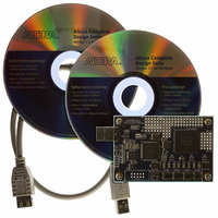
KIT MAX II MICRO
Manufacturer
Terasic Technologies Inc
Series
MAX® IIr
Type
FPGAr
Datasheet
1.P0305.pdf
(26 pages)
Specifications of P0305
Contents
Evaluation Board, Cable(s), Software and Documentation
For Use With/related Products
EPM2210F324
Lead Free Status / RoHS Status
Lead free / RoHS Compliant


2.5
The MAX II Micro board provides two modes, JTAG Mode and USB Blaster Mode, which allows
users to use the MAX II Micro board as a CPLD development board or as a USB Blaster cable,
respectively.
2.5.1
Users should use JTAG mode in normal operation. Set Swtich1 to UP position and set Switch2 to
DOWN position as shown in Figure 2.8.
Figure 2.8. Set Switch1 to UP position and Switch2 to DOWN position in normal operation (JTAG
2.5.2
This section describes how to use MAX II Micro as a USB Blaster Cable. Simply follow the
instructions below to finish the
need to solder a 10-pin header onto the board as show in Figure 2.9.
Note: The USB blaster cable function only supports JTAG programming mode.
1.
Connect the USB cable to the USB port on your PC and to the USB-Blaster port of MAX II
Micro board.
M ethods to Configure the MAX II Micro Board
9 B
C onfigure the MAX II Micro board in JTAG Mode
1 0 B
U se MAX II Micro as a USB Blaster Cable
1 1 B
Figure 2.9. Solder a 10-pin header onto the MAX II Micro board
setting. Before using MAX II Micro board as a USB Blaster, you
mode)
11
MMK User Manual
Related parts for P0305
Image
Part Number
Description
Manufacturer
Datasheet
Request
R

Part Number:
Description:
MODULE DIGITAL CAMERA 5MP (D5M)
Manufacturer:
Terasic Technologies Inc
Datasheet:

Part Number:
Description:
DE2-70 CALL FOR ACADEMIC PRICING
Manufacturer:
Terasic Technologies Inc
Datasheet:

Part Number:
Description:
USB BLASTER CABLE
Manufacturer:
Terasic Technologies Inc
Datasheet:

Part Number:
Description:
BOARD ADAPTER HSMC TO GPIO
Manufacturer:
Terasic Technologies Inc
Datasheet:

Part Number:
Description:
BOARD ADAPTER THDB-SUM
Manufacturer:
Terasic Technologies Inc
Datasheet:

Part Number:
Description:
KIT DEV 4.3" LCD TOUCH PANEL
Manufacturer:
Terasic Technologies Inc
Datasheet:

Part Number:
Description:
DAUGHTER BOARD AD/DA GPIO ADA
Manufacturer:
Terasic Technologies Inc

Part Number:
Description:
DAUGHTER BOARD AD/DA HSMC ADA
Manufacturer:
Terasic Technologies Inc

Part Number:
Description:
BOARD DEV/EDUCATION ALTERA DE0
Manufacturer:
Terasic Technologies Inc
Datasheet:

Part Number:
Description:
BOARD DEV DE1 ALTERA
Manufacturer:
Terasic Technologies Inc
Datasheet:

Part Number:
Description:
DE2 CALL FOR ACADEMIC PRICING
Manufacturer:
Terasic Technologies Inc

Part Number:
Description:
MODULE DIGITAL CAMERA 1.3MP
Manufacturer:
Terasic Technologies Inc
Datasheet:

Part Number:
Description:
SENSOR CMOS 1.3MEGA (FOR P0349)
Manufacturer:
Terasic Technologies Inc
Datasheet:
Part Number:
Description:
MODULE DIGITAL CAMERA 5MP (D5M)
Manufacturer:
Terasic Technologies Inc
Datasheet: