EVL6566B-65W STMicroelectronics, EVL6566B-65W Datasheet - Page 28
EVL6566B-65W
Manufacturer Part Number
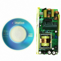
EVL6566B-65W
Description
BOARD EVAL FOR L6566B
Manufacturer
STMicroelectronics
Specifications of EVL6566B-65W
Main Purpose
AC/DC, Primary Side
Outputs And Type
1, Isolated
Power - Output
65W
Voltage - Output
12V
Current - Output
5.4A
Voltage - Input
90 ~ 265VAC
Regulator Topology
Flyback
Frequency - Switching
80kHz
Board Type
Fully Populated
Utilized Ic / Part
L6566B
Product
Power Management Modules
Lead Free Status / RoHS Status
Lead free / RoHS Compliant
Other names
497-6452
Available stocks
Company
Part Number
Manufacturer
Quantity
Price


Application information
Note:
28/51
setpoint. This is illustrated in the diagram on the left-hand side of
shows the relationship between the voltage on the pin VFF and V
saturated high in the attempt of keeping output voltage regulation):
Equation 5
Figure 16. Typical power capability change vs input voltage in QR flyback
If the voltage on the pin exceeds 3 V switching ceases but the soft-start capacitor is not
discharged. The schematic in
in the control loop.
With a proper selection of the external divider R1-R2, i.e. of the ratio k = R2 / (R1+R2), it is
possible to achieve the optimum compensation described by the lower curve in the diagram
of
The optimum value of k, k
voltage range, is the one that provides equal power capability at the extremes of the range.
The exact calculation is complex, and non-idealities shift the real-world optimum value from
the theoretical one. It is therefore more practical to provide a first cut value, simple to be
calculated, and then to fine tune experimentally.
Assuming that the system operates exactly at the boundary between DCM and CCM, and
neglecting propagation delays, the following expression for k
Equation 6
Figure 16
.
converters
2.5
1.5
0.5
2
1
k
1
opt
opt
=
, which minimizes the power capability variation over the input
Figure 17 on page 29
3
⋅
1.5
V
V
csx
in
min
=
⋅
1
V
2
−
in
max
V
VFF
3
V
+
inmin
V
2.5
(
in
=
V
V
compensated
system optimally
R
in
system not
compensated
1
min
−
shows also how the function is included
k
3
+
Vin
V
3
in
max
opt
)
can be found:
⋅
3.5
csx
V
Figure 17 on page 29
R
k = k
(with the error amplifier
k = 0
k
opt
4
L6566B
: it
Related parts for EVL6566B-65W
Image
Part Number
Description
Manufacturer
Datasheet
Request
R

Part Number:
Description:
BOARD EVAL SMPS FOR L6566B
Manufacturer:
STMicroelectronics
Datasheet:

Part Number:
Description:
BOARD EVAL FOR L6566B
Manufacturer:
STMicroelectronics
Datasheet:

Part Number:
Description:
BOARD EVAL FOR L6566B
Manufacturer:
STMicroelectronics
Datasheet:

Part Number:
Description:
Power Management Modules & Development Tools L6566B-60WQR Eval Board
Manufacturer:
STMicroelectronics
Part Number:
Description:
STMicroelectronics [RIPPLE-CARRY BINARY COUNTER/DIVIDERS]
Manufacturer:
STMicroelectronics
Datasheet:
Part Number:
Description:
STMicroelectronics [LIQUID-CRYSTAL DISPLAY DRIVERS]
Manufacturer:
STMicroelectronics
Datasheet:

Part Number:
Description:
BOARD EVAL FOR MEMS SENSORS
Manufacturer:
STMicroelectronics
Datasheet:
Part Number:
Description:
NPN TRANSISTOR POWER MODULE
Manufacturer:
STMicroelectronics
Datasheet:
Part Number:
Description:
TURBOSWITCH ULTRA-FAST HIGH VOLTAGE DIODE
Manufacturer:
STMicroelectronics
Datasheet:
Part Number:
Description:
Manufacturer:
STMicroelectronics
Datasheet:
Part Number:
Description:
DIODE / SCR MODULE
Manufacturer:
STMicroelectronics
Datasheet:
Part Number:
Description:
DIODE / SCR MODULE
Manufacturer:
STMicroelectronics
Datasheet: