EVL6566B-65W STMicroelectronics, EVL6566B-65W Datasheet
EVL6566B-65W
Specifications of EVL6566B-65W
Available stocks


Related parts for EVL6566B-65W


EVL6566B-65W Summary of contents
Page 1
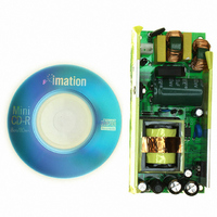
... This note describes the characteristics and the features reference board, wide-range input mains, AC-DC adapter using the L6566B controller. The peculiarities of this design are the low standby input consumption (<200mW@265Vinac), low cost and small size. Figure 1: EVL6566B-65W Adapter demo-board August 2005 APPLICATION NOTE ...
Page 2
APPLICATION NOTE Main characteristics and circuit description • UNIVERSAL INPUT MAINS RANGE: • OUTPUT VOLTAGE: • MAINS HARMONICS: • ST-BY MAINS CONSUMPTION: • OVERALL EFFICIENCY: • EMI: • SAFETY: • DIMENSIONS: • PCB: Circuit description The topology of this converter ...
Page 3
APPLICATION NOTE Figure 2: Electrical diagram 3/11 ...
Page 4
APPLICATION NOTE Test Results Efficiency measurements at full load In table 1 the converter overall efficiency measurement at nominal load (5.42 A) and different input voltage are reported. In table 2 the efficiency measurements according to the Energy Star regulation ...
Page 5
... Burst mode @90V-60Hz – No load operation CH1: Q101 Drain voltage CH2: L6566B Vcc (pin #5) Figure 4: EVL6566B-65W Waveforms @230V-50Hz – Full load CH1: Q7 Drain voltage CH2: Q7 Gate voltage CH3: VCC Figure 6: EVL6566B-65W Burst mode @265V-60Hz – No load operation CH1: Q101 Drain voltage CH2: L6566B Vcc (pin #5) 5/11 ...
Page 6
APPLICATION NOTE In Table 3, the input power consumption at no load is reported: as visible, thanks to the L6566B stand-by functions, the input power remains always below 200mW. Table 3: Input power at no load vs. mains voltage Vin ...
Page 7
APPLICATION NOTE Open Loop Protection (OVP) In figure 9 and shown the circuit behaviour simulating an open loop condition by opening R17. Once the voltage on ZCD pin connected to the transformer auxiliary winding by a divider ...
Page 8
APPLICATION NOTE Bill of material Table 4: EVAL6566B-65W: Bill of Material Reference Part name BR1 DB 4A 600V C2 100uF - 25V C3 100nF C4 470u - 25V C5 470u - 25V C7 470u - 16V C8 2.2nF C9 100nF ...
Page 9
APPLICATION NOTE R11A 300K R11B 300K R11C 300K R14 10R R15 12K R17 23K4 R18 27K R19 6K2 R19A 100R R19B 100R R22 2K7 R23 22K R45 3M R46 3M T1 ERL28-12PIN TH1 NTC 10R U1 TSM1014AIDT U5 L6566B U4 ...
Page 10
APPLICATION NOTE TRANSFORMER specification PIN DISTANCE: 5.08 mm PIN ROW DISTANCE: 30.5 mm PINS # are removed – Pin 3, 9 are for insertion polarity key. MECHANICAL ASPECT AND PIN NUMBERING 1 5. ...
Page 11
APPLICATION NOTE Electrical diagram and winding characteristics PINS: 6-2 21mm x 0.1mm Copper Shielding connected to pin 5 10-11 21mm x 0.1mm Copper Shielding connected to pin 5 2-4 1-5 NUMBER WINDING OF TURNS PRIMARY - B 28 12V 8 ...