EVL6566B-65W STMicroelectronics, EVL6566B-65W Datasheet - Page 19
EVL6566B-65W
Manufacturer Part Number
EVL6566B-65W
Description
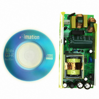
BOARD EVAL FOR L6566B
Manufacturer
STMicroelectronics
Specifications of EVL6566B-65W
Main Purpose
AC/DC, Primary Side
Outputs And Type
1, Isolated
Power - Output
65W
Voltage - Output
12V
Current - Output
5.4A
Voltage - Input
90 ~ 265VAC
Regulator Topology
Flyback
Frequency - Switching
80kHz
Board Type
Fully Populated
Utilized Ic / Part
L6566B
Product
Power Management Modules
Lead Free Status / RoHS Status
Lead free / RoHS Compliant
Other names
497-6452
Available stocks
Company
Part Number
Manufacturer
Quantity
Price


L6566B
With reference to the timing diagram of
the voltage on the bulk capacitor (Vin) builds up and, at about 80 V, the HV generator is
enabled to operate (HV_EN is pulled high) so that it draws about 1 mA. This current, minus
the device’s consumption, charges the bypass capacitor connected from pin Vcc (5) to
ground and makes its voltage rise almost linearly.
Figure 6.
As the Vcc voltage reaches the turn-on threshold (14 V typ.) the device starts operating and
the HV generator is cut off by the Vcc_OK signal asserted high. The device is powered by
the energy stored in the Vcc capacitor until the self-supply circuit (typically an auxiliary
winding of the transformer and a steering diode) develops a voltage high enough to sustain
the operation. The residual consumption of this circuit is just the one on the 15 MΩ resistor
(≈10 mW at 400 Vdc), typically 50-70 times lower, under the same conditions, as compared
to a standard start-up circuit made with external dropping resistors.
At converter power-down the system will lose regulation as soon as the input voltage is so
low that either peak current or maximum duty cycle limitation is tripped. Vcc will then drop
and stop IC activity as it falls below the UVLO threshold (10 V typ.). The Vcc_OK signal is
de-asserted as the Vcc voltage goes below a threshold VCC
generator can now restart. However, if Vin < Vin
asserted too and the HV generator is disabled. This prevents converter’s restart attempts
and ensures monotonic output voltage decay at power-down in systems where brownout
protection (see the relevant section) is not used.
The low restart threshold VCC
the device will have a very low repetition rate, as shown in the timing diagram of
page 20
Vcc_OK
(pin 5)
(pin 4)
HV_EN
Vcc
0.85 mA
V
I
Vcc
Vcc
GD
charge
HVstart
Vcc
restart
Vin
OFF
ON
, and that the converter will work safely with extremely low power throughput.
Timing diagram: normal power-up and power-down sequences
Power-on
rest
ensures that, during short circuits, the restart attempts of
Figure 6
, when power is first applied to the converter
start
operation
Normal
, as illustrated in
rest
located at about 5V. The HV
Application information
Figure 6
Power-off
regulation is lost here
, HV_EN is de-
Figure 7 on
19/51
t
t
t
t
t
t
Related parts for EVL6566B-65W
Image
Part Number
Description
Manufacturer
Datasheet
Request
R

Part Number:
Description:
BOARD EVAL SMPS FOR L6566B
Manufacturer:
STMicroelectronics
Datasheet:

Part Number:
Description:
BOARD EVAL FOR L6566B
Manufacturer:
STMicroelectronics
Datasheet:

Part Number:
Description:
BOARD EVAL FOR L6566B
Manufacturer:
STMicroelectronics
Datasheet:

Part Number:
Description:
Power Management Modules & Development Tools L6566B-60WQR Eval Board
Manufacturer:
STMicroelectronics
Part Number:
Description:
STMicroelectronics [RIPPLE-CARRY BINARY COUNTER/DIVIDERS]
Manufacturer:
STMicroelectronics
Datasheet:
Part Number:
Description:
STMicroelectronics [LIQUID-CRYSTAL DISPLAY DRIVERS]
Manufacturer:
STMicroelectronics
Datasheet:

Part Number:
Description:
BOARD EVAL FOR MEMS SENSORS
Manufacturer:
STMicroelectronics
Datasheet:
Part Number:
Description:
NPN TRANSISTOR POWER MODULE
Manufacturer:
STMicroelectronics
Datasheet:
Part Number:
Description:
TURBOSWITCH ULTRA-FAST HIGH VOLTAGE DIODE
Manufacturer:
STMicroelectronics
Datasheet:
Part Number:
Description:
Manufacturer:
STMicroelectronics
Datasheet:
Part Number:
Description:
DIODE / SCR MODULE
Manufacturer:
STMicroelectronics
Datasheet:
Part Number:
Description:
DIODE / SCR MODULE
Manufacturer:
STMicroelectronics
Datasheet: