FEB178 Fairchild Semiconductor, FEB178 Datasheet
FEB178
Specifications of FEB178


Related parts for FEB178


FEB178 Summary of contents
Page 1
... FAN5350MPX -40°C to 85°C For Fairchild’s definition of Eco Status, please visit: http://www.fairchildsemi.com/company/green/rohs_green.html. Please refer to tape and reel specifications at www.fairchildsemi.com; http://www.fairchildsemi.com/packaging. © 2007 Fairchild Semiconductor Corporation FAN5350 Rev. 1.0.5 Description The FAN5350 is a step-down switching voltage regulator that delivers a fixed 1.82V from an input voltage supply of 2 ...
Page 2
... VIN GND Figure 1. WLCSP, Bumps Facing Down Block Diagram Bias EN 1.8V Reference FB © 2007 Fairchild Semiconductor Corporation FAN5350 Rev. 1.0 1µH 4.7µF V OUT C OUT 4.7µF C OUT Current Limit + Modulator Logic - 3MHz OSC Zero Crossing Figure 3. Block Diagram 2 ...
Page 3
... Enable Pin. The device is in shutdown mode when voltage to this pin is <0.4V and enabled 4 EN when >1.2V. Do not leave this pin floating Switching Node. Connection to the internal PFET switch and NFET synchronous rectifier Power Supply Input. IN © 2007 Fairchild Semiconductor Corporation FAN5350 Rev. 1.0.5 GND SW FB Figure 5. WLCSP - Bumps Facing Up PGND VIN ...
Page 4
... Junction-to-ambient thermal resistance is a function of application and board layout. This data is measured with four-layer 1s2p boards in accordance to JESD51- JEDEC standard. Special attention must be paid not to exceed junction temperature T © 2007 Fairchild Semiconductor Corporation FAN5350 Rev. 1.0.5 Parameter Human Body Model Charged Device Model ...
Page 5
... LIM T Thermal Shutdown TSD T Thermal Shutdown Hysteresis HYS Note: 2. The Electrical Characteristics table reflects open-loop data. Refer to Operation Description and Typical Characteristic for closed-loop data. © 2007 Fairchild Semiconductor Corporation FAN5350 Rev. 1.0.5 = 2.7V to 5.5V -40°C to +85° 25°C, V =3.6V Conditions ...
Page 6
... Fairchild Semiconductor Corporation FAN5350 Rev. 1.0.5 Enable and Soft Start Maintaining the EN pin LOW keeps the FAN5350 in ...
Page 7
... Inductor Value I MAX(LOAD) Increase Increase Decrease Decrease © 2007 Fairchild Semiconductor Corporation FAN5350 Rev. 1.0.5 The increased RMS current produces higher losses through the R inductor ESR. Increasing the inductor value produces lower RMS currents, but degrades transient response. For a given physical inductor size, increased inductance usually results in an inductor with lower saturation current ...
Page 8
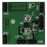
... Capacitor 4.7μF, ±10%, 6.3V, X5R, 0603 IC DC/DC Regulator in CSP, 5 bumps Load Resistor (Optional) Figure 7. The FAN5350 Evaluation Board PCB (CSP) © 2007 Fairchild Semiconductor Corporation FAN5350 Rev. 1.0.5 ensures that the control sections of the IC do not behave erratically due to excessive noise. This reduces switching cycle jitter and ensures good overall performance ...
Page 9
... Load Current (A) Figure 12. DC Current Voltage Output Characteristics © 2007 Fairchild Semiconductor Corporation FAN5350 Rev. 1.0.5 , according to the circuit in Figure 1 or Figure 2, unless otherwise specified. 1850 1840 +85°C 1830 +25° ...
Page 10
... Ambient Temperature (°C) Figure 16. PMOS Current Limit in Closed Loop 85dB 5dB /div 35dB 1Hz 10Hz Figure 18. Power Supply Rejection Ratio in CCM © 2007 Fairchild Semiconductor Corporation FAN5350 Rev. 1.0.5 (Continued) , according to the circuit in Figure 1 or Figure 2, unless otherwise specified. 100 V =2. ...
Page 11
... Figure 20. Startup, Full Load H scale: 1µs / div. Figure 22. Fast Load Transient, No Load to Full Load H scale: 20µs / div. Figure 24. Fast Load Transient in CCM © 2007 Fairchild Semiconductor Corporation FAN5350 Rev. 1.0.5 (Continued) , according to the circuit in Figure 1 or Figure 2, unless otherwise specified 0.5A / div. ...
Page 12
... Figure 28. Line Transient, 600mV, 50mA Load Figure 30. Combined Line (600mV) and Load (100mA to 350mA) Transient Response H scale: 1µs / div. Figure 31. Typical Waveforms in DCM, 50mA Load © 2007 Fairchild Semiconductor Corporation FAN5350 Rev. 1.0.5 (Continued) , according to the circuit in Figure 1 or Figure 2, unless otherwise specified. ...
Page 13
... Package drawings are provided as a service to customers considering Fairchild components. Drawings may change in any manner without notice. Please note the revision and/or date on the drawing and contact a Fairchild Semiconductor representative to verify or obtain the most recent revision. Package specifications do not expand the terms of Fairchild’s worldwide terms and conditions, specifically the warranty therein, which covers Fairchild products. Always visit Fairchild Semiconductor’ ...
Page 14
... Package drawings are provided as a service to customers considering Fairchild components. Drawings may change in any manner without notice. Please note the revision and/or date on the drawing and contact a Fairchild Semiconductor representative to verify or obtain the most recent revision. Package specifications do not expand the terms of Fairchild’s worldwide terms and conditions, specifically the warranty therein, which covers Fairchild products. Always visit Fairchild Semiconductor’ ...
Page 15
... Fairchild Semiconductor Corporation FAN5350 Rev. 1.0.5 15 www.fairchildsemi.com ...