RDK-138 Power Integrations, RDK-138 Datasheet
RDK-138
Specifications of RDK-138


Related parts for RDK-138


RDK-138 Summary of contents
Page 1
... The products and applications illustrated herein (including circuits external to the products and transformer construction) may be covered by one or more U.S. and foreign patents or potentially by pending U.S. and foreign patent applications assigned to Power Integrations. A complete list of Power Integrations’ patents may be found at www.powerint.com. ...
Page 2
... Although this board is designed to satisfy safety isolation requirements, the engineering prototype has not been agency approved. Therefore, all testing should be performed using an isolation transformer to provide the AC input to the prototype board. Power Integrations Tel: +1 408 414 9200 Fax: +1 408 414 9201 www.powerint.com ...
Page 3
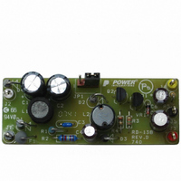
... LNK304DN device that provides two output voltages. The document contains the power supply specification, schematic, bill of materials, transformer documentation, printed circuit layout, and performance data. Figure 1 – Populated Circuit Board Photograph. Page Power Integrations Tel: +1 408 414 9200 Fax: +1 408 414 9201 www.powerint.com ...
Page 4
... P OUT Environmental Conducted EMI Safety Surge Differential Mode Ambient Temperature 1 CEC does not apply to this design but data are shown for reference. Power Integrations Tel: +1 408 414 9200 Fax: +1 408 414 9201 www.powerint.com Symbol Min Typ Max 85 265 V ...
Page 5
... With respect to RTN (J4), the supply provides outputs of – & with pins 1 & JP1 shorted. When pins 2 & JP1 are shorted, the supply provides +5 V and +12 V with respect to RTN (J5). Page Figure 2 – Schematic. Tel: +1 408 414 9200 Fax: +1 408 414 9201 Power Integrations www.powerint.com ...
Page 6
... The device is powered from the drain pin with local supply decoupling provided by the 100 nF capacitor C3 connected to the bypass pin (BP) of the LinkSwitch-TN device, U1. Power Integrations Tel: +1 408 414 9200 Fax: +1 408 414 9201 www.powerint.com ...
Page 7
... D2 and D3’s forward voltages are equal, and thus the feedback network tracks the output voltage. Page The on time of the MOSFET is determined by the output Tel: +1 408 414 9200 Fax: +1 408 414 9201 During D2’s ≤75 ns (In this case the BYV26C rr Power Integrations www.powerint.com ...
Page 8
... An optional pre-load resistor, R5, is placed on the output to maintain better than ±5% voltage regulation on this output. As the transistors Q1 and Q2 are physically close to one another, they provide better thermal tracking by cancelling V helping to maintain good regulation. Power Integrations Tel: +1 408 414 9200 Fax: +1 408 414 9201 www.powerint.com variations, thereby ...
Page 9
... PCB Layout Page Figure 3 – Printed Circuit Layout. Tel: +1 408 414 9200 Fax: +1 408 414 9201 Power Integrations www.powerint.com ...
Page 10
... RF1 Wire Wound LinkSwitch-TN, LNK304DN, SO VR1 5.1 V, 500 mW, 5%, DO-35 All Parts shown are RoHS compliant Power Integrations Tel: +1 408 414 9200 Fax: +1 408 414 9201 www.powerint.com Mfg Mfg Part Number Taicon Corporation TAQ2G4R7MK0811MLL3 Kemet C317C104M5U5TA Nippon Chemi-Con EKMG500ELL100ME11D Nippon ...
Page 11
... W ≥ ≤ > Page Efficiency vs. Load 50% 75% Load Percent ) Minimum Efficiency in Active Mode of Operation O 0.50 × P 0.09 × 0.50 [ln = natural log] O 0.85 Tel: +1 408 414 9200 Fax: +1 408 414 9201 115 VAC 230 VAC 100% Minimum active mode O Power Integrations www.powerint.com ...
Page 12
... CEC standard does not apply to this design, the data are provided for reference. More states within the USA and other countries are adopting this standard. For the latest information, please visit the PI Green Room: http://www.powerint.com/greenroom/regulations.htm Power Integrations Tel: +1 408 414 9200 Fax: +1 408 414 9201 www.powerint.com Efficiency (%) Percent of ...
Page 13
... Input Voltage (VAC) , and the 5 V load current was swept from I O(12VMIN) , and the 12 V load current was swept from I O(5VMIN) Tel: +1 408 414 9200 Fax: +1 408 414 9201 215 235 255 275 O(5VMIN) O(12VMAX). O(12VMIN) O(5VMAX). Power Integrations www.powerint.com ...
Page 14
... Figure 6 – Load Line and Load Regulation (5 V Min / Max Load, 85 VAC and 265 VAC), 25 ºC. 4.0% 3.5% 3.0% 2.5% 2.0% 1.5% 1.0% 0.5% 0. Figure 7 – Load Line and Load Regulation (12 V Min / Max Load, 85 VAC and 265 VAC), 25 ºC. Power Integrations Tel: +1 408 414 9200 Fax: +1 408 414 9201 www.powerint.com Load Current (mA Load Current (mA) ...
Page 15
... Line Full Load Output Regulation vs. Input Voltage 125 Figure 8 – Line Regulation, Room Temperature, Full Load. Page 175 225 Input Voltage (VAC) Tel: +1 408 414 9200 Fax: +1 408 414 9201 12 V Output 5 V Output 275 Power Integrations www.powerint.com ...
Page 16
... Thermal Performance Table 2 shows the thermal performance at 50 ºC ambient temperature. Device (U1) Anode of Output Diode (D2) Collector of Transistor (Q2) Output Inductor (L2) Power Integrations Tel: +1 408 414 9200 Fax: +1 408 414 9201 www.powerint.com Temperature (°C) Item 86 VAC Ambient Table 2 – Thermal Measurements Taken. Figure 9 – Top Side Thermal Image. ...
Page 17
... Figure 12 – 265 VAC, V Upper: V Lower: I Figure 14 – Start-up Profile, 265 VAC. Upper Output div. Lower Output /div. Time base div. Tel: +1 408 414 9200 Fax: +1 408 414 9201 To V Full Load. DC SOURCE, , 200 V / div, 5 µs/div. SOURCE , 0 div. DRAIN Power Integrations www.powerint.com ...
Page 18
... Source Voltage and Drain Current Start-up Profile Figure 15 – 85 VAC Input and Maximum Load. Upper Lower 0 div. DRAIN Time base div. Power Integrations Tel: +1 408 414 9200 Fax: +1 408 414 9201 www.powerint.com Figure 16 – 265 VAC Input and Maximum , 50 V. SOURCE Load. Upper 200 V ...
Page 19
... Output. Upper Output div. Lower Load Current div. Timebase div. Page Figure 18 – Transient Response, 265 VAC. 75-100-75% Load Step Output. Upper Output div. Bottom Load Current div. Timebase div. Power Integrations Tel: +1 408 414 9200 Fax: +1 408 414 9201 www.powerint.com ...
Page 20
... Figure 19 – Transient Response, 85 VAC. 75-100-75% Load Step Output. Upper Output div. Lower Load Current div. Timebase div. Power Integrations Tel: +1 408 414 9200 Fax: +1 408 414 9201 www.powerint.com Figure 20 – Transient Response, 265 VAC. 75-100-75% Load Step Output. Upper Output div. ...
Page 21
... Figure 21 – Oscilloscope Probe Prepared for Ripple Measurement. (End Cap and Ground Lead Removed) Figure 22 – Oscilloscope Probe with Probe Master (www.probemaster.com) 4987A BNC Adapter. (Modified with Wires for Ripple Measurement, and Two Parallel Decoupling Capacitors Added) Page Probe Ground Probe Tip Power Integrations Tel: +1 408 414 9200 Fax: +1 408 414 9201 www.powerint.com ...
Page 22
... Measurement Results Figure 23 – Ripple, 85 VAC, Full Load div div. Figure 25 – Ripple, 85 VAC, Full Load /div. Power Integrations Tel: +1 408 414 9200 Fax: +1 408 414 9201 www.powerint.com Figure 24 – Ripple, 265 VAC, Full Load div div. Figure 26 – Ripple, 265 VAC, Full Load. ...
Page 23
... Figure 27 – Worst Case Conducted EMI, Measured at Full Load, 230 VAC Input, 60 Hz, Neutral Figure 28 – Worst Case Conducted EMI, Measured at Full Load, 115 VAC Input, 60 Hz, Neutral Page Conductor, EN55022B Limits Shown. Conductor, EN55022B Limits Shown. Tel: +1 408 414 9200 Fax: +1 408 414 9201 Power Integrations www.powerint.com ...
Page 24
... Unit passes under all test conditions. Power Integrations Tel: +1 408 414 9200 Fax: +1 408 414 9201 www.powerint.com Input Injection Injection Voltage Location (VAC) 230 230 230 230 230 230 230 ...
Page 25
... Revision History Date Author 12-Nov-07 KM Page Revision Description & changes 1.0 Initial Release. Tel: +1 408 414 9200 Fax: +1 408 414 9201 Reviewed Power Integrations www.powerint.com ...
Page 26
... Power Integrations Tel: +1 408 414 9200 Fax: +1 408 414 9201 www.powerint.com Notes Page ...
Page 27
... Page Notes Power Integrations Tel: +1 408 414 9200 Fax: +1 408 414 9201 www.powerint.com ...
Page 28
... For the latest updates, visit our website: www.powerint.com Power Integrations reserves the right to make changes to its products at any time to improve reliability or manufacturability. Power Integrations does not assume any liability arising from the use of any device or circuit described herein. POWER INTEGRATIONS MAKES NO WARRANTY HEREIN AND SPECIFICALLY DISCLAIMS ALL WARRANTIES INCLUDING, WITHOUT LIMITATION, THE IMPLIED WARRANTIES OF MERCHANTABILITY, FITNESS FOR A PARTICULAR PURPOSE, AND NON-INFRINGEMENT OF THIRD PARTY RIGHTS ...