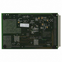
EVAL-AD7725CBZ Analog Devices Inc, EVAL-AD7725CBZ Datasheet - Page 10

EVAL-AD7725CBZ
Manufacturer Part Number
EVAL-AD7725CBZ
Description
BOARD EVALUATION FOR AD7725
Manufacturer
Analog Devices Inc
Datasheet
1.AD7725BSZ.pdf
(28 pages)
Specifications of EVAL-AD7725CBZ
Number Of Adc's
1
Number Of Bits
16
Sampling Rate (per Second)
900k
Data Interface
Serial, Parallel
Inputs Per Adc
1 Differential
Input Range
±VREF
Power (typ) @ Conditions
615mW @ 900kSPS
Voltage Supply Source
Analog and Digital
Operating Temperature
-40°C ~ 85°C
Utilized Ic / Part
AD7725
Lead Free Status / RoHS Status
Lead free / RoHS Compliant
AD7725
Pin No.
5
6
7
8
9, 10
11
12
13
14
15
16, 18
17
19
20
21
22
23
24
25
26
Mnemonic S/P
DVAL/INT
DGND
RD/WR
S/P
AGND1
AV
CLKIN
XTAL
XTALOFF
HALF_PWR
AGND
AV
V
V
REF1
AGND2
REF2
UNI
AGND
AV
IN
IN
DD1
DD
(–)
(+)
DD
Oscillator Enable Input. A logic high disables the crystal oscillator amplifier to allow the use
Logic Input. When this input is low, the typical analog current is 50 mA and a maximum
Description
Serial Mode. DVAL–Data Valid Logic Output. This output is low when there are no
overflows in the postprocessor and goes high when an overflow occurs in the postprocessor.
Parallel Mode. INT–Interrupt Logic Output. INT idles low. A logic high on this output pin
indicates that user intervention is required. There are several cases when this may occur:
•
•
•
•
•
Ground Reference for Digital Circuitry.
Serial Mode. This input is not used in serial mode and should be tied to DGND.
Parallel Mode. Read/Write Logic Input. This input is used in conjunction with the CS
input to read data from or write data to the device. A read cycle is initiated when RD/WR
is high. A write cycle is initiated when RD/WR is low. To read or write data, CS should be low.
Serial/Parallel Interface Select. When S/P is tied low, parallel mode is selected. Serial
mode is selected when S/P is tied high. To change the mode, a full power cycle needs
to be performed.
Digital Logic Power Supply Ground for the Analog Modulator.
Digital Logic Power Supply for the Analog Modulator.
Clock Input. An external clock source can be applied directly to this pin with XTALOFF
tied high. Alternatively, a parallel resonant fundamental frequency crystal, in parallel with a
1 M resistor, can be connected between the XTAL pin and the CLKIN pin with
XTALOFF tied low. External capacitors are then required from the CLKIN and XTAL
pins to ground. Consult the crystal manufacturer’s recommendation for the load capacitors.
In both cases, once power is applied to the AD7725, the clock input has to be continual.
Input to Crystal Oscillator Amplifier. If an external clock is used, XTAL should be tied
to AGND1.
of an external clock source. Set low to enable the crystal oscillator amplifier when using an
external crystal between the CLKIN and XTAL pins.
CLKIN frequency of 14.4 MHz applies. When this input is high, the analog current typically
halves and a maximum CLKIN frequency of 9.6 MHz applies.
Power Supply Ground for the Analog Modulator.
Power Supply Voltage for the Analog Modulator.
Negative Terminal of the Differential Analog Input.
Positive Terminal of the Differential Analog Input.
Reference Output. REF1 is connected to the output of the internal 2.5 V reference through a
3 k resistor and to a reference buffer amplifier that drives the - modulator. When the
internal reference is used, a 1 µF capacitor is required between REF1 and AGND to decouple
the band gap noise and REF2 should be decoupled to AGND with a 220 nF and a 10 nF
capacitor in parallel.
Power Supply Ground for the Reference Circuitry, REF2, of the Analog Modulator.
Reference Input. REF2 connects to the output of an external buffer amplifier used to drive
the - modulator. When REF2 is used as an input, REF1 must be connected to AGND
to disable the internal buffer amplifier.
Analog Input Range Select Input. The UNI pin selects the analog input range for either
bipolar (differential or single-ended input) or unipolar (single-ended input) operation. A
logic high input selects unipolar operation and a logic low input selects bipolar operation.
Power Supply Ground for the Analog Modulator.
Power Supply Voltage for the Analog Modulator.
An instruction is completed. Writing an instruction or reading the status register clears
the interrupt.
Write data is requested. Writing data clears the interrupt.
Read data is ready. Reading data clears the interrupt.
An error occurs – ID or CRC error in the configuration file format, or an overflow in
the postprocessor. Reading the status register clears the interrupt.
The device completes power-on reset. Reading the status register clears the interrupt.
–10–
REV. A


