MCP3909EV-MCU16 Microchip Technology, MCP3909EV-MCU16 Datasheet - Page 22
MCP3909EV-MCU16
Manufacturer Part Number
MCP3909EV-MCU16
Description
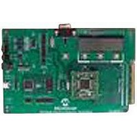
EVALUATION BOARD FOR MCP3909
Manufacturer
Microchip Technology
Datasheets
1.MCP3909T-ISS.pdf
(44 pages)
2.MCP3909T-ISS.pdf
(104 pages)
3.MCP3909EV-MCU16.pdf
(38 pages)
Specifications of MCP3909EV-MCU16
Number Of Adc's
2
Number Of Bits
16
Sampling Rate (per Second)
15k
Data Interface
Serial
Inputs Per Adc
1 Differential
Input Range
±1 V
Voltage Supply Source
Analog and Digital
Operating Temperature
-40°C ~ 85°C
Utilized Ic / Part
MCP3909
Silicon Manufacturer
Microchip
Application Sub Type
ADC
Kit Application Type
Data Converter
Silicon Core Number
MCP3909
Kit Contents
Board
Lead Free Status / RoHS Status
Lead free / RoHS Compliant


MCP3909 ADC Evaluation Board for 16-Bit MCUs User’s Guide
3.2
3.3
3.4
DS51777A-page 18
SETTING THE SAMPLE RATE
CONNECTIVITY, RECORDING LENGTH AND CALIBRATION OF DATA
SCOPE PLOT WINDOW - TIME DOMAIN ANALYSIS
On the MCP3909 ADC Evaluation Board for 16-Bit MCUs is possible to select from five
different sampling rates, referred here as gears. The control is placed in the up left
areas of the GUI.
The value of the sampling rate for each gear is as follows:
• 1
• 2
• 3
• 4
• 5
Once the gear is changed, the actualized value of the sampling rate is indicated on the
“Sampling Frequency (sps)” field. The “Frequency Resolution” field will indicate the
space between spectral lines of the sampled signal, at the indicated sample rate.
Changing the sampling rate in the GUI will not automatically change the one on the
MCP3909 ADC Evaluation Board for 16-Bit MCUs. For this to happen it is necessary
to manually change the gear, by pressing the RB9 button placed on the board.
The PC is connected to the MCP3909 ADC Evaluation Board for 16-Bit MCUs through
the RS232 cable. It is important to have a COM port on the PC. It is possible to use a
USB to RS232 adaptor cable, for this case being necessary to write the number of the
virtual COM port. To do this, right-click on My computer > Manage > Device Manager
> Port (COM and LPT), and read the number in the parenthesis, after the device name.
The COM port number must be selected in the “VISA Resource Name” field.
The MCU is sending a big packet of data to the PC. If the user need to see only to a
small part of the buffer, he will write the desired buffer length in the “Buffer length” field.
The maximum length is 512 samples.
The user have the option to choose between Calibrate and Not Calibrate tab from the
up-right corner of the window. The calibration is possible for an AC signal
measurement, calibrating the scale and selecting the desired unit of measure for the
processed data.
When selecting the Calibrate tab, two fields are shown: the “Amplitude CH0” and the
“Amplitude CH1”, with the corresponding Calibration buttons. The user must write the
peak-to-peak value in the two fields, and then press the Calibration button for each,
or use the shortcuts (<F2> for CH0 and <F3> for CH1). If the Calibration button is not
pressed, or the shortcut is not applied, plot screens will be empty.
If the Not Calibrated tab is selected, the “Amplitude” fields and Calibration buttons are
not visible, and the data plotted on the screen will be indicated in LSBs (in ADC code).
To stop the GUI it is necessary to press the STOP button, or the <F4> shortcut key.
The recorded samples from a buffer are indicated on the “Waveform Graphs” screens.
The size of the X scale is given by the number showed in the “Buffer Length” field.
If the Not Calibrated tab is selected, the value on Y axis will be given by the LSBs. If
the data is calibrated, and calibration value is 0.5, for example, the data on the
waveform graphs will have an amplitude peak-to-peak of 2x0.5. It is important to note
that the offset is not removed.
st
nd
th
th
th
gear
gear
gear
gear
gear
- 644.2 sps
- 2963 sps
- 4938 sps
- 8888 sps
- 14813 sps
© 2008 Microchip Technology Inc.
Related parts for MCP3909EV-MCU16
Image
Part Number
Description
Manufacturer
Datasheet
Request
R

Part Number:
Description:
Manufacturer:
Microchip Technology Inc.
Datasheet:
Part Number:
Description:
Manufacturer:
Microchip Technology Inc.
Datasheet:
Part Number:
Description:
Manufacturer:
Microchip Technology Inc.
Datasheet:
Part Number:
Description:
Manufacturer:
Microchip Technology Inc.
Datasheet:
Part Number:
Description:
Manufacturer:
Microchip Technology Inc.
Datasheet:
Part Number:
Description:
Manufacturer:
Microchip Technology Inc.
Datasheet:
Part Number:
Description:
Manufacturer:
Microchip Technology Inc.
Datasheet:
Part Number:
Description:
Manufacturer:
Microchip Technology Inc.
Datasheet: