MCP3909EV-MCU16 Microchip Technology, MCP3909EV-MCU16 Datasheet - Page 15
MCP3909EV-MCU16
Manufacturer Part Number
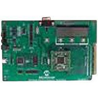
MCP3909EV-MCU16
Description
EVALUATION BOARD FOR MCP3909
Manufacturer
Microchip Technology
Datasheets
1.MCP3909T-ISS.pdf
(44 pages)
2.MCP3909T-ISS.pdf
(104 pages)
3.MCP3909EV-MCU16.pdf
(38 pages)
Specifications of MCP3909EV-MCU16
Number Of Adc's
2
Number Of Bits
16
Sampling Rate (per Second)
15k
Data Interface
Serial
Inputs Per Adc
1 Differential
Input Range
±1 V
Voltage Supply Source
Analog and Digital
Operating Temperature
-40°C ~ 85°C
Utilized Ic / Part
MCP3909
Silicon Manufacturer
Microchip
Application Sub Type
ADC
Kit Application Type
Data Converter
Silicon Core Number
MCP3909
Kit Contents
Board
Lead Free Status / RoHS Status
Lead free / RoHS Compliant


2.1
© 2008 Microchip Technology Inc.
DSPIC33 FIRMWARE DESCRIPTION
2.1.1
After reset, the code jumps to line 305 from main.c file, where the initialization routine
is called: Initialization(). First, the nested interrupts are disabled. External
interrupt 3 is enabled on the negative edge. Timer 2 is running on the Output
Compare 1, being used to generate the clock for the MCP3909. In addition, some initial
values are set up for the MCP3909 clock frequency.
Timer 5 is enabled and set to generate an interrupt at compare mach; the time period
between two interrupts is a few hundred milliseconds.
The SPI module is initialized and started, but the corresponding interrupt is not
enabled. UART transmitter is initialized, but the corresponding interrupt is not enabled.
Communication speed is set for 115200 baud. The UART receiver is not used.
Pins with analogue alternate function are setup as digital-input outputs. Initial values
for different variables are being set at the end of the initialization routine.
Back in the void main() routine the nested interrupts are enabled. Then the routine
that starts the MCP3909 is called: startMCP3909().
2.1.2
During this routine the MCP3909 is put into a test mode, according to the MCP3909
data sheet. At the beginning CS and MCP3909 reset pins (MCLR) have high values.
After a slight delay, MCLR is toggled low, and then the serial command b10100100 is
sent to the device. This means that the ADC is placed into “Dual Channel Output PRE
HPF1” mode. Then, a short positive pulse is sent to CS.
2.1.3
In the main() file, the LCD will display the samples values.
At this point, the Main routine will enter an infinite loop. All the other tasks are being
done during the interrupt routines.
2.1.4
All events that don't need to take place to a repeated, constant period of time are
processed during this interrupt. One event that is happening at the time of this routine
is the blinking of LED D7 - as a life sign for the system. This routine is monitoring the
buttons state (pressed or not pressed), and also counts how many times each of them
have been pressed.
Note:
Reset and Initialization
startMCP3909()
Main()
Timer 5 Compare Mach Interrupt
The time period can be changed from PR5 register.
Chapter 2. Firmware
MCP3909 ADC EVALUATION BOARD
FOR 16-BIT MCUs USER’S GUIDE
DS51777A-page 11
Related parts for MCP3909EV-MCU16
Image
Part Number
Description
Manufacturer
Datasheet
Request
R

Part Number:
Description:
Manufacturer:
Microchip Technology Inc.
Datasheet:
Part Number:
Description:
Manufacturer:
Microchip Technology Inc.
Datasheet:
Part Number:
Description:
Manufacturer:
Microchip Technology Inc.
Datasheet:
Part Number:
Description:
Manufacturer:
Microchip Technology Inc.
Datasheet:
Part Number:
Description:
Manufacturer:
Microchip Technology Inc.
Datasheet:
Part Number:
Description:
Manufacturer:
Microchip Technology Inc.
Datasheet:
Part Number:
Description:
Manufacturer:
Microchip Technology Inc.
Datasheet:
Part Number:
Description:
Manufacturer:
Microchip Technology Inc.
Datasheet: