MCP3909EV-MCU16 Microchip Technology, MCP3909EV-MCU16 Datasheet - Page 17
MCP3909EV-MCU16
Manufacturer Part Number
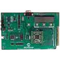
MCP3909EV-MCU16
Description
EVALUATION BOARD FOR MCP3909
Manufacturer
Microchip Technology
Datasheets
1.MCP3909T-ISS.pdf
(44 pages)
2.MCP3909T-ISS.pdf
(104 pages)
3.MCP3909EV-MCU16.pdf
(38 pages)
Specifications of MCP3909EV-MCU16
Number Of Adc's
2
Number Of Bits
16
Sampling Rate (per Second)
15k
Data Interface
Serial
Inputs Per Adc
1 Differential
Input Range
±1 V
Voltage Supply Source
Analog and Digital
Operating Temperature
-40°C ~ 85°C
Utilized Ic / Part
MCP3909
Silicon Manufacturer
Microchip
Application Sub Type
ADC
Kit Application Type
Data Converter
Silicon Core Number
MCP3909
Kit Contents
Board
Lead Free Status / RoHS Status
Lead free / RoHS Compliant


2.2
2.3
2.4
© 2008 Microchip Technology Inc.
DISPLAY MODE CONTROL - SW2
SAMPLING SPEED RATE CONTROL - SW3
DATA ACQUISITION
Table 2-1 describes the actions made to the SW2 button, and the results shown on the
LCD.
TABLE 2-1:
SW3 button is used to control the sampling speed rate of the ADC by changing the
frequency of the MCP3909 clock signal.
The initial sampling frequency rate is around 640 sps. For a 64 sample buffer it means
a 0.1s recording buffer.
Table indicates estimated values for the sampling frequency when operating the SW3
button:
TABLE 2-2:
These higher sampling rates can be used when the measured signal has a high
frequency, or when a signal doesn't have a stable frequency and we want to measure
its amplitude. For higher sampling rate the measurement error induced by the Sinc filter
is reduced.
External interrupt 3 is used for detecting the end of conversion on MCP3909. Because
this line is the same with the SPI data output, the first thing done after the detection of
an external interrupt is to disable this particular interrupt. Otherwise an interrupt will be
generated on each falling edges of the SPI signal.
Then the setup for the SPI is changed: it will be used in 16-bit mode, and the interrupt
is activated. The SPIBUF register is being read to clear the SPI interrupt flag. For the
first 16 periods of SPI clock, 0 value will be send to the MCP3909.
The SPI interrupt takes place after each successful data transfer between master and
slave on SPI. As in any interrupt, first thing to do is to clear the interrupt flag, otherwise
a new interrupt will happen again, for no reason.
NEVER PRESSED
1
2
3
Pressed 1
Pressed 2
Pressed 3
Pressed 4
st
nd
rd
Note:
Time
Time
Time
Type of Operation
Type of Operation
st
nd
rd
th
Important! When using the GUI for evaluation, the ‘gear’ on the GUI must
be set to the speed on the board, i.e. 1
time
time
time
time
LCD MESSAGE DURING SW2 MANIPULATION
RESULTS DURING SW3 MANIPULATION
LCD indicates the same message as the one during the reset
time: samples values.
LCD shows the results of the FFT performed on CH0.
LCD shows the results of the FFT performed on samples
recorded from CH1.
LCD indicates the results form the auto-correlation function:
signal frequency and the index of maximum of the
auto-correlation function.
The sampling speed rate is to 2000 sps.
The sampling frequency rate is 3800 sps.
The sampling frequency rate is 7600 sps.
The sampling speed rate is 15000 sps.
Sampling Frequency Rate Estimation
LCD Screen Results
st
, 2
nd
, 3
rd
, etc.
Firmware
DS51777A-page 13
Related parts for MCP3909EV-MCU16
Image
Part Number
Description
Manufacturer
Datasheet
Request
R

Part Number:
Description:
Manufacturer:
Microchip Technology Inc.
Datasheet:
Part Number:
Description:
Manufacturer:
Microchip Technology Inc.
Datasheet:
Part Number:
Description:
Manufacturer:
Microchip Technology Inc.
Datasheet:
Part Number:
Description:
Manufacturer:
Microchip Technology Inc.
Datasheet:
Part Number:
Description:
Manufacturer:
Microchip Technology Inc.
Datasheet:
Part Number:
Description:
Manufacturer:
Microchip Technology Inc.
Datasheet:
Part Number:
Description:
Manufacturer:
Microchip Technology Inc.
Datasheet:
Part Number:
Description:
Manufacturer:
Microchip Technology Inc.
Datasheet: