MCP3909EV-MCU16 Microchip Technology, MCP3909EV-MCU16 Datasheet - Page 11
MCP3909EV-MCU16
Manufacturer Part Number
MCP3909EV-MCU16
Description
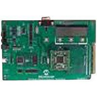
EVALUATION BOARD FOR MCP3909
Manufacturer
Microchip Technology
Datasheets
1.MCP3909T-ISS.pdf
(44 pages)
2.MCP3909T-ISS.pdf
(104 pages)
3.MCP3909EV-MCU16.pdf
(38 pages)
Specifications of MCP3909EV-MCU16
Number Of Adc's
2
Number Of Bits
16
Sampling Rate (per Second)
15k
Data Interface
Serial
Inputs Per Adc
1 Differential
Input Range
±1 V
Voltage Supply Source
Analog and Digital
Operating Temperature
-40°C ~ 85°C
Utilized Ic / Part
MCP3909
Silicon Manufacturer
Microchip
Application Sub Type
ADC
Kit Application Type
Data Converter
Silicon Core Number
MCP3909
Kit Contents
Board
Lead Free Status / RoHS Status
Lead free / RoHS Compliant


1.2
FIGURE 1-2:
© 2008 Microchip Technology Inc.
PIM MODULE / MCP3909 CONNECTION AND PERIPHERAL USAGE
OVERVIEW
PIM Module
RF2/U1RX
RF3/U1TX
SDO1/RF8
T2CK/RC1
SCK1/RF6
RB8/9/10
SDI1/RF7
OC1/RD0
RA9/10
RD11
RD10
RA5
RA4
The MCP3909 ADC Evaluation Board for 16-Bit MCUs contains a 100-pin PIM socket
compatible with Microchip’s PIM modules. The system comes with 2 PIM modules: the
PIC24FJ128GA010 and dsPIC33FJ256GA710.
A complete description of the firmware programmed with these two modules see in
Chapter 1. “Hardware Description”.
Digital Connection Overview PIM/MCP3909 connections.
Ports A, B, and D are used for signals such as push buttons, output LEDs, CS and
MCLR (for MCP3909 data mode setting). Output Capture 1 is used for MCP3909’s
clock generation. Serial communication is achieved through the MSSP module 1, and
the Timer2 Capture Compare can be used to measure MCP3909 active power output
frequency (HFOUT).
HFOUT
MCLR
SDI
SDO
SCK
CS
D6 D7
CONTROL SWITCHES (X3)
UART SERIAL TO PC COMMUNICATION
CLKIN
Frequency
Converter
Interface
Digital to
Clock
Generation
Serial
Block
(Green)
HPF
HPF1
HPF1
MCP3909
Hardware Description
Multi-level
Multi-level
ΔΣ ADC
ΔΣ ADC
16-bit
16-bit
G1
PGA
+
+
‚
‚
G0
DS51777A-page 7
CH0+
CH0-
CH1+
CH1-
Related parts for MCP3909EV-MCU16
Image
Part Number
Description
Manufacturer
Datasheet
Request
R

Part Number:
Description:
Manufacturer:
Microchip Technology Inc.
Datasheet:
Part Number:
Description:
Manufacturer:
Microchip Technology Inc.
Datasheet:
Part Number:
Description:
Manufacturer:
Microchip Technology Inc.
Datasheet:
Part Number:
Description:
Manufacturer:
Microchip Technology Inc.
Datasheet:
Part Number:
Description:
Manufacturer:
Microchip Technology Inc.
Datasheet:
Part Number:
Description:
Manufacturer:
Microchip Technology Inc.
Datasheet:
Part Number:
Description:
Manufacturer:
Microchip Technology Inc.
Datasheet:
Part Number:
Description:
Manufacturer:
Microchip Technology Inc.
Datasheet: