ADCLK950/PCBZ Analog Devices Inc, ADCLK950/PCBZ Datasheet - Page 6
ADCLK950/PCBZ
Manufacturer Part Number
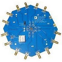
ADCLK950/PCBZ
Description
BOARD EVALUATION FOR ADCLK950
Manufacturer
Analog Devices Inc
Series
SIGer
Specifications of ADCLK950/PCBZ
Main Purpose
Timing, Clock Buffer / Driver / Receiver / Translator
Utilized Ic / Part
ADCLK950
Primary Attributes
2 Selectable Inputs, 10 Outputs
Secondary Attributes
LVPECL Output Logic
Silicon Manufacturer
Analog Devices
Application Sub Type
Clock Fanout Buffer
Kit Application Type
Clock & Timing
Silicon Core Number
ADCLK950
Lead Free Status / RoHS Status
Lead free / RoHS Compliant
Embedded
-
Lead Free Status / RoHS Status
Lead free / RoHS Compliant


ADCLK950
PIN CONFIGURATION AND FUNCTION DESCRIPTIONS
Table 7. Pin Function Descriptions
Pin No.
1
2
3
4
5
6
7
8
9
10
11, 20, 21,
30, 31, 40
12, 13
14, 15
16, 17
18, 19
22, 23, 28,
29
24, 25
26, 27
32, 33
34, 35
36, 37
38, 39
Mnemonic
IN_SEL
CLK0
CLK0
V
V
CLK1
CLK1
V
V
V
V
Q9, Q9
Q8, Q8
Q7, Q7
Q6, Q6
NC
Q5, Q5
Q4, Q4
Q3, Q3
Q2, Q2
Q1, Q1
Q0, Q0
EPAD
T
REF
EE
CC
REF
T
0
1
1
0
Description
Input Select. Logic 0 selects CLK0 and CLK0 inputs. Logic 1 selects CLK1 and CLK1 inputs.
Differential Input (Positive) 0.
Differential Input (Negative) 0.
Reference Voltage. Reference voltage for biasing ac-coupled CLK0 and CLK0 inputs.
Center Tap. Center tap of a 100 Ω input resistor for CLK0 and CLK0 inputs.
Differential Input (Positive) 1.
Differential Input (Negative) 1.
Center Tap. Center tap of a 100 Ω input resistor for CLK1 and CLK1 inputs.
Reference Voltage. Reference voltage for biasing ac-coupled CLK1 and CLK1 inputs.
Negative Supply Pin.
Positive Supply Pin.
Differential LVPECL Outputs.
Differential LVPECL Outputs.
Differential LVPECL Outputs.
Differential LVPECL Outputs.
No Connection
Differential LVPECL Outputs.
Differential LVPECL Outputs.
Differential LVPECL Outputs.
Differential LVPECL Outputs.
Differential LVPECL Outputs.
Differential LVPECL Outputs.
Exposed pad (EPAD) must be connected to V
IN_SEL
NOTES
1. NC = NO CONNECT.
2. EPAD MUST BE SOLDERED TO V
V
V
CLK0
CLK0
CLK1
CLK1
REF
REF
V
V
V
EE
T
T
0
0
1
1
10
1
2
3
4
5
6
7
8
9
Figure 2. Pin Configuration
PIN 1
INDICATOR
Rev. A | Page 6 of 12
ADCLK950
(Not to Scale)
TOP VIEW
EE
POWER PLANE.
EE
.
30 V
29 NC
28 NC
27 Q4
26 Q4
25 Q5
24 Q5
23 NC
22 NC
21 V
CC
CC
Related parts for ADCLK950/PCBZ
Image
Part Number
Description
Manufacturer
Datasheet
Request
R

Part Number:
Description:
±1.7g Dual-Axis IMEMS Accelerometer Evaluation Board
Manufacturer:
Analog Devices Inc
Datasheet:

Part Number:
Description:
Inertial Sensor Evaluation System
Manufacturer:
Analog Devices Inc
Datasheet:
Part Number:
Description:
Manufacturer:
Analog Devices Inc
Datasheet:
Part Number:
Description:
Manufacturer:
Analog Devices Inc
Datasheet:
Part Number:
Description:
Manufacturer:
Analog Devices Inc
Datasheet:
Part Number:
Description:
Manufacturer:
Analog Devices Inc
Datasheet:
Part Number:
Description:
Manufacturer:
Analog Devices Inc
Datasheet:
Part Number:
Description:
Manufacturer:
Analog Devices Inc
Datasheet:
Part Number:
Description:
Manufacturer:
Analog Devices Inc
Datasheet:
Part Number:
Description:
Manufacturer:
Analog Devices Inc
Datasheet:
Part Number:
Description:
Manufacturer:
Analog Devices Inc
Datasheet:
Part Number:
Description:
Manufacturer:
Analog Devices Inc
Datasheet:
Part Number:
Description:
Manufacturer:
Analog Devices Inc
Datasheet: