MCP215XDM Microchip Technology, MCP215XDM Datasheet - Page 44
MCP215XDM
Manufacturer Part Number
MCP215XDM
Description
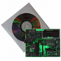
BOARD DEMO FOR MCP215X
Manufacturer
Microchip Technology
Specifications of MCP215XDM
Main Purpose
Interface, IrDA
Embedded
Yes, MCU, 8-Bit
Utilized Ic / Part
MCP2150, MCP2155
Primary Attributes
IrDA Controller with PIC18F MCU
Secondary Attributes
Set up as a Data Logger with LCD, GUI, Socket for EEPROM, Battery Powerable
Processor To Be Evaluated
MCP2150
Silicon Manufacturer
Microchip
Silicon Core Number
MCP2150, MCP2155
Kit Application Type
Interface
Application Sub Type
Standard Protocol Stack Controller
Kit Contents
Board
Rohs Compliant
Yes
Lead Free Status / RoHS Status
Lead free / RoHS Compliant
Lead Free Status / RoHS Status
Lead free / RoHS Compliant, Lead free / RoHS Compliant
Other names
MCP215XDMR
MCP215XDMR
MCP215XDMR
Available stocks
Company
Part Number
Manufacturer
Quantity
Price
Company:

Part Number:
MCP215XDM
Manufacturer:
MICROCHIP
Quantity:
12 000


MCP215X Data Logger Demo Board User’s Guide
DS51516A-page 40
TABLE 2-10:
TX
RX
RI
DSR
DTR
CTS
RTS
CD
Legend: TTL = TTL compatible input
Name
Pin
I = Input
Number
(PDIP)
Pin
MCP2150 HOST UART INTERFACE PINS
10
11
12
13
14
19
8
9
Type
Pin
O
O
O
I
I
I
I
I
Buffer
Type
TTL
TTL
TTL
TTL
ST
—
—
—
ST = Schmitt Trigger input with CMOS levels
O = Output
Asynchronous receive; from Host Controller UART.
Asynchronous transmit; to Host Controller UART.
Ring Indicator. The value on this pin is driven high.
Data Set Ready. Indicates that the MCP2150 has
completed reset:
1 = MCP2150 is initialized.
0 = MCP2150 is not initialized.
Data Terminal Ready. The value of this pin is
ignored once the MCP2150 is initialized. It is
recommended that this pin be connected so that
the voltage level is either V
At device power-up, this signal is used with the
RTS signal to enter device ID programming.
1 = Enter device ID programming mode
(if RTS is cleared).
0 = Do not enter device ID programming mode.
Clear-to-Send. Indicates that the MCP2150 is
ready to receive data form the Host Controller. This
signal is locally emulated and not related to the
CTS/RTS bit of the IrDA
1 = Host Controller should not send data.
0 = Host Controller may send data.
Request-to-Send. Indicates that a Host Controller
is ready to receive data from the MCP2150. This
signal is locally emulated and not related to the
CTS/RTS bit of the IrDA standard Primary device.
1 = Host Controller not ready to receive data.
0 = Host Controller ready to receive data.
At device power-up, this signal is used with the
DTR signal to enter device ID programming.
1 = Do not enter device ID programming mode.
0 = Enter device ID programming mode
(if DTR is set).
Carrier Detect. Indicates that the MCP2150 has
established a valid link with a Primary Device.
1 = An IR link has not been established
(No IR Link).
0 = An IR link has been established (IR link).
Description
2004 Microchip Technology Inc.
®
standard Primary device.
SS
or V
CC
.
Related parts for MCP215XDM
Image
Part Number
Description
Manufacturer
Datasheet
Request
R

Part Number:
Description:
Manufacturer:
Microchip Technology Inc.
Datasheet:
Part Number:
Description:
Manufacturer:
Microchip Technology Inc.
Datasheet:
Part Number:
Description:
Manufacturer:
Microchip Technology Inc.
Datasheet:
Part Number:
Description:
Manufacturer:
Microchip Technology Inc.
Datasheet:
Part Number:
Description:
Manufacturer:
Microchip Technology Inc.
Datasheet:
Part Number:
Description:
Manufacturer:
Microchip Technology Inc.
Datasheet:
Part Number:
Description:
Manufacturer:
Microchip Technology Inc.
Datasheet:
Part Number:
Description:
Manufacturer:
Microchip Technology Inc.
Datasheet: