MCP215XDM Microchip Technology, MCP215XDM Datasheet - Page 34
MCP215XDM
Manufacturer Part Number
MCP215XDM
Description
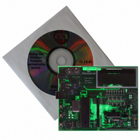
BOARD DEMO FOR MCP215X
Manufacturer
Microchip Technology
Specifications of MCP215XDM
Main Purpose
Interface, IrDA
Embedded
Yes, MCU, 8-Bit
Utilized Ic / Part
MCP2150, MCP2155
Primary Attributes
IrDA Controller with PIC18F MCU
Secondary Attributes
Set up as a Data Logger with LCD, GUI, Socket for EEPROM, Battery Powerable
Processor To Be Evaluated
MCP2150
Silicon Manufacturer
Microchip
Silicon Core Number
MCP2150, MCP2155
Kit Application Type
Interface
Application Sub Type
Standard Protocol Stack Controller
Kit Contents
Board
Rohs Compliant
Yes
Lead Free Status / RoHS Status
Lead free / RoHS Compliant
Lead Free Status / RoHS Status
Lead free / RoHS Compliant, Lead free / RoHS Compliant
Other names
MCP215XDMR
MCP215XDMR
MCP215XDMR
Available stocks
Company
Part Number
Manufacturer
Quantity
Price
Company:

Part Number:
MCP215XDM
Manufacturer:
MICROCHIP
Quantity:
12 000


MCP215X Data Logger Demo Board User’s Guide
TABLE 2-6:
DS51516A-page 30
1
2
3
4
5
6
7
Step Action
Place both devices on a flat surface about 25 cm (10”)
apart and with the IR ports facing each other.
On the MCP215X Data Logger Demo Board:
Ensure that jumpers JP1 and JP2 are shorted (closed
position).
On the MCP215X Data Logger Demo Board:
Ensure that jumper JP7 is shorted (closed position).
On the MCP215X Data Logger Demo Board:
Insert the 9V battery into the battery holder (BT1) or
plug a 9V AC-to-DC power supply (such as those
supplied with some Microchip development tools) into
the 9V DC Connection Plug (J2).
You may need to depress the RESET switch if the
LCD does not display the Microchip program revision
information and then the directions for demo program
selection.
On the MCP215X Data Logger Demo Board:
Depress Switch 2 (SW2).
On the PDA:
Start the IrDA
On the PDA:
Tap on the Connect button.
VENDING MACHINE DEMO - POCKET PC
®
2.4.2.2
After saving the AN941 application program to your PC’s hard drive, the PC can
communicate with the MCP215X Data Logger Demo Board. Section 2.4.2.2.1 “Steps
to Operate the Vending Machine Demo” discusses how to operate the vending
machine program, while 2.4.2.2.2 “Steps to Operate the 250-byte S -> P Data Trans-
fer Demo” discusses how to operate the 250-byte Secondary device (S) to Primary
device (P) data transfer program.
2.4.2.2.1
The vending machine demo is shown by following the steps in Table 2-6.
Demo program.
RUNNING THE DEMO USING THE APPLICATION NOTE 926 PROGRAM
Steps to Operate the Vending Machine Demo
Result
—
—
—
On the MCP215X Data Logger Demo Board:
The green power LED (D10) will turn on, the DTR
LED will be on, while all the other UART Flow Control
signals (CTS, RTS, CD, RI and DSR) will be off. Also
the RD7 and RD6 LEDs will be on.
On the MCP215X Data Logger Demo Board:
This causes the vending machine program to be
executed.
On the PDA:
The screen will display the IrDA Demo program
window, with the “Device ID” line displaying “Generic
IrDA”, while the “IR Link” line displays “Discovery
Mode”.
On the PDA:
Once the connection is made, the program window
will be updated so that the Connect button is called
the Disconnect button and the “IR Link” line displays
“Normal Response Mode”.
On the MCP215X Data Logger Demo Board:
The CD LED will turn on and the CTS LED will strobe
rapidly and then return to the normal rate. This
indicates that an IR link is established between the
PDA and the demo board.
2004 Microchip Technology Inc.
Related parts for MCP215XDM
Image
Part Number
Description
Manufacturer
Datasheet
Request
R

Part Number:
Description:
Manufacturer:
Microchip Technology Inc.
Datasheet:
Part Number:
Description:
Manufacturer:
Microchip Technology Inc.
Datasheet:
Part Number:
Description:
Manufacturer:
Microchip Technology Inc.
Datasheet:
Part Number:
Description:
Manufacturer:
Microchip Technology Inc.
Datasheet:
Part Number:
Description:
Manufacturer:
Microchip Technology Inc.
Datasheet:
Part Number:
Description:
Manufacturer:
Microchip Technology Inc.
Datasheet:
Part Number:
Description:
Manufacturer:
Microchip Technology Inc.
Datasheet:
Part Number:
Description:
Manufacturer:
Microchip Technology Inc.
Datasheet: