MCP215XDM Microchip Technology, MCP215XDM Datasheet - Page 37
MCP215XDM
Manufacturer Part Number
MCP215XDM
Description
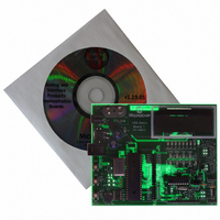
BOARD DEMO FOR MCP215X
Manufacturer
Microchip Technology
Specifications of MCP215XDM
Main Purpose
Interface, IrDA
Embedded
Yes, MCU, 8-Bit
Utilized Ic / Part
MCP2150, MCP2155
Primary Attributes
IrDA Controller with PIC18F MCU
Secondary Attributes
Set up as a Data Logger with LCD, GUI, Socket for EEPROM, Battery Powerable
Processor To Be Evaluated
MCP2150
Silicon Manufacturer
Microchip
Silicon Core Number
MCP2150, MCP2155
Kit Application Type
Interface
Application Sub Type
Standard Protocol Stack Controller
Kit Contents
Board
Rohs Compliant
Yes
Lead Free Status / RoHS Status
Lead free / RoHS Compliant
Lead Free Status / RoHS Status
Lead free / RoHS Compliant, Lead free / RoHS Compliant
Other names
MCP215XDMR
MCP215XDMR
MCP215XDMR
Available stocks
Company
Part Number
Manufacturer
Quantity
Price
Company:

Part Number:
MCP215XDM
Manufacturer:
MICROCHIP
Quantity:
12 000


TABLE 2-7:
2004 Microchip Technology Inc.
8
9
10
11
12
13
14
Step
On the MCP215X Data Logger Demo Board:
Depress Switch 2 or Switch 3 to select which flavor of
the transmit program is executed.
On the PDA:
Tap on the Get File button.
On the PDA:
Tap on the Trace button.
On the PDA:
Tap on the Clear button.
On the PDA:
Tap on the Close button.
Step 8 through Step 12 may be repeated.
On the PDA:
Tap on the Disconnect button.
250-BYTE S -> P DATA TRANSFER DEMO - POCKET PC (CONTINUED)
Action
—
On the MCP215X Data Logger Demo Board:
If Switch SW2 is depressed, then the Host Controller
will only transmit data to the MCP2150 while the CTS
signal is low. The LCD will indicate that the MCP215X
Data Logger Demo Board is waiting to receive a data
byte from the Primary device.
If Switch SW3 is depressed, the Host Controller will
transmit 64 bytes of data to the MCP2150 when the
CTS signal goes low. The LCD will indicate that the
MCP215X Data Logger Demo Board is waiting to
receive a data byte from the Primary device.
On the MCP215X Data Logger Demo Board:
The CTS LED will strobe rapidly and then return to the
normal rate.
The second line of the LCD will display the text
"Transmitting" and, once the data table has been sent,
the text will change to "TX Complete".
After approx. 1 second, the PIC16F877 will return to
the routine used to select how the 250-byte table is
transmitted (see Step 8). The LCD will display the
options.
On the PDA:
The data is received in the program’s trace buffer.
On the PDA:
This opens the trace buffer window. You may scroll up
and down in this window to view the received data.
On the PDA:
This clears the data that is in the trace buffer window.
On the PDA:
This closes the trace buffer window.
On the PDA:
This will disconnect (close) the IR link. When the IR
Link is closed, the program window will be updated so
that the Disconnect button changes back to the
Connect button. The “IR Link” line will display “Normal
Disconnect Mode” and then, after a couple of
seconds, will display “Discovery Mode”.
On the MCP215X Data Logger Demo Board:
The CD and the CTS LEDs will turn off.
Installation and Operation
Result
DS51516A-page 33
Related parts for MCP215XDM
Image
Part Number
Description
Manufacturer
Datasheet
Request
R

Part Number:
Description:
Manufacturer:
Microchip Technology Inc.
Datasheet:
Part Number:
Description:
Manufacturer:
Microchip Technology Inc.
Datasheet:
Part Number:
Description:
Manufacturer:
Microchip Technology Inc.
Datasheet:
Part Number:
Description:
Manufacturer:
Microchip Technology Inc.
Datasheet:
Part Number:
Description:
Manufacturer:
Microchip Technology Inc.
Datasheet:
Part Number:
Description:
Manufacturer:
Microchip Technology Inc.
Datasheet:
Part Number:
Description:
Manufacturer:
Microchip Technology Inc.
Datasheet:
Part Number:
Description:
Manufacturer:
Microchip Technology Inc.
Datasheet: