MCP215XDM Microchip Technology, MCP215XDM Datasheet - Page 24
MCP215XDM
Manufacturer Part Number
MCP215XDM
Description
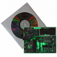
BOARD DEMO FOR MCP215X
Manufacturer
Microchip Technology
Specifications of MCP215XDM
Main Purpose
Interface, IrDA
Embedded
Yes, MCU, 8-Bit
Utilized Ic / Part
MCP2150, MCP2155
Primary Attributes
IrDA Controller with PIC18F MCU
Secondary Attributes
Set up as a Data Logger with LCD, GUI, Socket for EEPROM, Battery Powerable
Processor To Be Evaluated
MCP2150
Silicon Manufacturer
Microchip
Silicon Core Number
MCP2150, MCP2155
Kit Application Type
Interface
Application Sub Type
Standard Protocol Stack Controller
Kit Contents
Board
Rohs Compliant
Yes
Lead Free Status / RoHS Status
Lead free / RoHS Compliant
Lead Free Status / RoHS Status
Lead free / RoHS Compliant, Lead free / RoHS Compliant
Other names
MCP215XDMR
MCP215XDMR
MCP215XDMR
Available stocks
Company
Part Number
Manufacturer
Quantity
Price
Company:

Part Number:
MCP215XDM
Manufacturer:
MICROCHIP
Quantity:
12 000


MCP215X Data Logger Demo Board User’s Guide
DS51516A-page 20
2.3.2.2
After the MCP215X Data Logger Demo Board has completed reset and the LCD mod-
ule indicates which switches to depress to select a program, depress switches S2 and
S3 simultaneously. The LCD module will indicate that the 250-byte S P program is
selected.
You then need to specify the data transfer method. The host UART interface is
operating at 115,200 baud. There are two methods by which to accomplish this.
In the first method, the PIC16F877 will transfer data to the MCP2150 while the CTS
signal is low. This is the easiest method to implement. To select this method, depress
switch S2. After depressing S2, the LCD will indicate the mode of data transfer and that
it is waiting. The transfer will not commence until the PIC16F877 has received a data
byte from the Primary device.
In the second method, the PIC16F877 will transfer 64 bytes of the data table to the
MCP2150 after the falling edge of the CTS signal. This method gives the best data
throughput. To select this method, depress switch S3. After depressing S3, the LCD will
indicate the mode of data transfer and that it is waiting. The transfer will not commence
until the PIC16F877 has received a data byte from the Primary device.
The PIC16F877 follows the flow control of the MCP2150 to ensure that data is not lost.
The MCP2150 handles all the IrCOMM protocol for the data packets that it receives
from the PIC16F877.
After the table has completed transmission, the PIC16F877 returns to the routine that
asks for the data transfer method.
The program flow for the “250 Byte Secondary Device (S) to Primary Device (P) Data
Transfer” demo is shown in Figure 2-7.
The 250-byte data table transmitted from the MCP215X Data Logger Demo Board to
the Primary device is shown in Appendix D. “MCP215X 250-Byte Data Transmit
Table”. These values will be displayed in the Primary device’s terminal emulation
program window.
The PIC16F877 receives a single byte from the IrDA standard Primary device and then
a 250-byte table is transmitted back to the Primary device.
If you desire more than 250 bytes to be transferred, the source code is written to allow
this 250-byte table to be transmitted multiple times. At the beginning of the S P Data
Transfer routine (routine has label S2Pxfer), there is a #define for the TableCNTR.
This is set to ‘1’, but can be changed to allow the data table to be transmitted
“TableCNTR” time. TableCNTR should not be greater than D’255’ (8-bit value)
Note:
250-BYTE SECONDARY DEVICE (S) TO PRIMARY DEVICE DATA
TRANSFER PROGRAM DESCRIPTION
The byte sent by the Primary device is expected since most PDAs will not
establish a link until data is sent.
Depending on the PDA application program used (Palm™ or Pocket PC),
the operation of the Connect button varies.
2004 Microchip Technology Inc.
Related parts for MCP215XDM
Image
Part Number
Description
Manufacturer
Datasheet
Request
R

Part Number:
Description:
Manufacturer:
Microchip Technology Inc.
Datasheet:
Part Number:
Description:
Manufacturer:
Microchip Technology Inc.
Datasheet:
Part Number:
Description:
Manufacturer:
Microchip Technology Inc.
Datasheet:
Part Number:
Description:
Manufacturer:
Microchip Technology Inc.
Datasheet:
Part Number:
Description:
Manufacturer:
Microchip Technology Inc.
Datasheet:
Part Number:
Description:
Manufacturer:
Microchip Technology Inc.
Datasheet:
Part Number:
Description:
Manufacturer:
Microchip Technology Inc.
Datasheet:
Part Number:
Description:
Manufacturer:
Microchip Technology Inc.
Datasheet: