MCP215XDM Microchip Technology, MCP215XDM Datasheet - Page 19
MCP215XDM
Manufacturer Part Number
MCP215XDM
Description
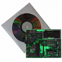
BOARD DEMO FOR MCP215X
Manufacturer
Microchip Technology
Specifications of MCP215XDM
Main Purpose
Interface, IrDA
Embedded
Yes, MCU, 8-Bit
Utilized Ic / Part
MCP2150, MCP2155
Primary Attributes
IrDA Controller with PIC18F MCU
Secondary Attributes
Set up as a Data Logger with LCD, GUI, Socket for EEPROM, Battery Powerable
Processor To Be Evaluated
MCP2150
Silicon Manufacturer
Microchip
Silicon Core Number
MCP2150, MCP2155
Kit Application Type
Interface
Application Sub Type
Standard Protocol Stack Controller
Kit Contents
Board
Rohs Compliant
Yes
Lead Free Status / RoHS Status
Lead free / RoHS Compliant
Lead Free Status / RoHS Status
Lead free / RoHS Compliant, Lead free / RoHS Compliant
Other names
MCP215XDMR
MCP215XDMR
MCP215XDMR
Available stocks
Company
Part Number
Manufacturer
Quantity
Price
Company:

Part Number:
MCP215XDM
Manufacturer:
MICROCHIP
Quantity:
12 000


TABLE 2-1:
2004 Microchip Technology Inc.
Legend: S = Jumper is shorted (Closed)
Note 1:
Jumper
JP1
JP2
JP3
JP4
JP5
JP6
JP7
#
This is the jumper settings for using the integrated transceiver where the PIC16F877 controls the baud
rate and the PORTD LEDs are used.
Settings
Typical
N/A
N/A
O
S
S
S
S
JUMPER DESCRIPTIONS AND SETTINGS
(1)
A description of the MCP215X Data Logger Demo Board jumpers is given in Table 2-1.
To connect TXIR of MCP2150 to TXD of U5 (TFDS 4500)
S = TXIR connected to TXD
O = TXIR Not connected to TXD
To connect RXIR of MCP2150 to RXD of U5 (TFDS 4500)
S = RXIR connected to RXD
O = RXIR Not connected to RXD
To connect EN of MCP2150 to V
S = MCP2150 in Low-power mode
O = MCP2150 during normal operation
To connect cathode of LEDs (RD7:RD0) to V
S = Cathode of LEDs to V
O = Cathode of LEDs floating
To control source of MCP2150 BAUD1 pin
To control source of MCP2150 BAUD0 pin
To connect V
4500
DD
to integrated optical transceiver (U5) - TFDS
O = Jumper is Open
Description
SS
SS
SS
Installation and Operation
When Open, the signal can
come from the daughter
board connected to Header
J1/J5.
When Open, the signal can
come from the daughter
board connected to Header
J1/J5.
The PCB default state is
shorted between jumper. No
jumper is required.
Comment
DS51516A-page 15
Related parts for MCP215XDM
Image
Part Number
Description
Manufacturer
Datasheet
Request
R

Part Number:
Description:
Manufacturer:
Microchip Technology Inc.
Datasheet:
Part Number:
Description:
Manufacturer:
Microchip Technology Inc.
Datasheet:
Part Number:
Description:
Manufacturer:
Microchip Technology Inc.
Datasheet:
Part Number:
Description:
Manufacturer:
Microchip Technology Inc.
Datasheet:
Part Number:
Description:
Manufacturer:
Microchip Technology Inc.
Datasheet:
Part Number:
Description:
Manufacturer:
Microchip Technology Inc.
Datasheet:
Part Number:
Description:
Manufacturer:
Microchip Technology Inc.
Datasheet:
Part Number:
Description:
Manufacturer:
Microchip Technology Inc.
Datasheet: