MCP215XDM Microchip Technology, MCP215XDM Datasheet - Page 42
MCP215XDM
Manufacturer Part Number
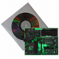
MCP215XDM
Description
BOARD DEMO FOR MCP215X
Manufacturer
Microchip Technology
Specifications of MCP215XDM
Main Purpose
Interface, IrDA
Embedded
Yes, MCU, 8-Bit
Utilized Ic / Part
MCP2150, MCP2155
Primary Attributes
IrDA Controller with PIC18F MCU
Secondary Attributes
Set up as a Data Logger with LCD, GUI, Socket for EEPROM, Battery Powerable
Processor To Be Evaluated
MCP2150
Silicon Manufacturer
Microchip
Silicon Core Number
MCP2150, MCP2155
Kit Application Type
Interface
Application Sub Type
Standard Protocol Stack Controller
Kit Contents
Board
Rohs Compliant
Yes
Lead Free Status / RoHS Status
Lead free / RoHS Compliant
Lead Free Status / RoHS Status
Lead free / RoHS Compliant, Lead free / RoHS Compliant
Other names
MCP215XDMR
MCP215XDMR
MCP215XDMR
Available stocks
Company
Part Number
Manufacturer
Quantity
Price
Company:

Part Number:
MCP215XDM
Manufacturer:
MICROCHIP
Quantity:
12 000


MCP215X Data Logger Demo Board User’s Guide
TABLE 2-9:
DS51516A-page 38
9
10
11
12
13
14
15
Step Action
In the IrDA standard demo PC program window:
Depress and release the Connect button.
On the PC:
If the PC is configured to show the IR icon in the
system tray, the single IR LED icon will change to an
icon of two IR LEDs facing each other and talking.
Place the mouse cursor over this icon.
In the IrDA standard demo PC program window:
In the TX Data (ASCII) entry box, type in any number
(such as “5”).
In the IrDA standard demo PC program window:
Depress and release the Send Byte button.
Step 7 through Step 12 may be repeated.
In the IrDA standard demo PC program window:
Depress and release the Disconnect button.
If the PC is configured to show the IR icon in the
system tray, a single IR LED will be displayed.
250 BYTE S -> P DATA TRANSFER DEMO - WINDOWS
Result
In the IrDA standard demo PC program window:
Once the connection is made, the program window
will be updated to show that the Connect button now
is called the Disconnect button.
On the MCP215X Data Logger Demo Board:
The CD LED will turn on and the CTS LED will flash.
This indicates that an IR link is established between
the PC and the demo board.
On the PC:
The message “Wireless link with Generic IrDA at
115200 bps” will be displayed. This shows that a link is
now established for data communication and that the
IR communication rate is 115200 bps, the baud rate
that was negotiated between the PC IrDA standard
hardware and the MCP2150.
—
On the MCP215X Data Logger Demo Board:
The CTS LED will strobe rapidly and then return to the
normal rate, with the PORTD LEDs showing the ASCII
value for the data byte transmitted (“5” = 0x35).
After approx. 1 second, the PIC16F877 will return to
the routine used to select how the 250-byte table is
transmitted (see Step 7). The LCD will display the
options.
In the IrDA standard demo PC program window:
The “Raw Received Data” window will display the
data table that was transmitted by the MCP215X Data
Logger Demo Board. This table is shown in
Appendix D. “MCP215X 250-Byte Data Transmit
Table”. The scroll bar may be used to inspect the
data received.
—
In the IrDA standard demo PC program window:
This will disconnect (close) the IR link. When the IR
link is disconnected, the PC icon will change to
indicate that the IR link is disconnected (has a red X).
On the MCP215X Data Logger Demo Board:
The CD and the CTS LEDs will turn off.
—
®
XP (CONTINUED)
2004 Microchip Technology Inc.
Related parts for MCP215XDM
Image
Part Number
Description
Manufacturer
Datasheet
Request
R

Part Number:
Description:
Manufacturer:
Microchip Technology Inc.
Datasheet:
Part Number:
Description:
Manufacturer:
Microchip Technology Inc.
Datasheet:
Part Number:
Description:
Manufacturer:
Microchip Technology Inc.
Datasheet:
Part Number:
Description:
Manufacturer:
Microchip Technology Inc.
Datasheet:
Part Number:
Description:
Manufacturer:
Microchip Technology Inc.
Datasheet:
Part Number:
Description:
Manufacturer:
Microchip Technology Inc.
Datasheet:
Part Number:
Description:
Manufacturer:
Microchip Technology Inc.
Datasheet:
Part Number:
Description:
Manufacturer:
Microchip Technology Inc.
Datasheet: