MCP215XDM Microchip Technology, MCP215XDM Datasheet - Page 50
MCP215XDM
Manufacturer Part Number
MCP215XDM
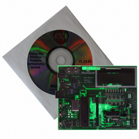
Description
BOARD DEMO FOR MCP215X
Manufacturer
Microchip Technology
Specifications of MCP215XDM
Main Purpose
Interface, IrDA
Embedded
Yes, MCU, 8-Bit
Utilized Ic / Part
MCP2150, MCP2155
Primary Attributes
IrDA Controller with PIC18F MCU
Secondary Attributes
Set up as a Data Logger with LCD, GUI, Socket for EEPROM, Battery Powerable
Processor To Be Evaluated
MCP2150
Silicon Manufacturer
Microchip
Silicon Core Number
MCP2150, MCP2155
Kit Application Type
Interface
Application Sub Type
Standard Protocol Stack Controller
Kit Contents
Board
Rohs Compliant
Yes
Lead Free Status / RoHS Status
Lead free / RoHS Compliant
Lead Free Status / RoHS Status
Lead free / RoHS Compliant, Lead free / RoHS Compliant
Other names
MCP215XDMR
MCP215XDMR
MCP215XDMR
Available stocks
Company
Part Number
Manufacturer
Quantity
Price
Company:

Part Number:
MCP215XDM
Manufacturer:
MICROCHIP
Quantity:
12 000


DS51516B-page 46
2.8.7
The MCP215X/40 Data Logger Demo Board offers three possible optical transceiver
circuits, only one is installed. The remaining circuits can be populated and evaluated.
The “default” optical transceiver circuit is a Vishay TFDU 4300 (U14). The JP1C1 and
JP2C1 jumpers are shorted by a trace on the bottom of the board, if these “shorting”
traces are cut, then a 1x2 jumper stakes should be installed. These traces would be cut
if either of the other two optical transceivers were to be installed or a daughter board
would be connected to headers J1 and J5.
Connecting the integrated optical transceiver is done by:
1. Ensure that all jumpers JP1x1 and JP2x1 are “open”
2. Shorting Jumper JP1x1 and JP2x1.
Now the integrated optical transceiver should be operational.
Note 1:
Note:
(unless using the Default selection, in which JP1C1 and JP2C1 will be shorted
by a trace wire, if this had not been previously cut open)
2:
3:
Using the Integrated Optical Transceiver (U5)
Remember that jumpers JMP1, JMP2, and JMP3 must be properly jum-
pered for the MCP215X/40 device installed
Only one optical transceiver circuit should be connected to the
MCP215X/40 device at a given time
If the trace between JP1C1 pin 1 and pin 2 have been cut, then a 1x2
jumper stakes should be installed so that the jumper can be shorted
If the trace between JP2C1 pin 1 and pin 2 have been cut, then a 1x2
jumper stakes should be installed so that the jumper can be shorted
© 2006 Microchip Technology Inc.
Related parts for MCP215XDM
Image
Part Number
Description
Manufacturer
Datasheet
Request
R

Part Number:
Description:
Manufacturer:
Microchip Technology Inc.
Datasheet:
Part Number:
Description:
Manufacturer:
Microchip Technology Inc.
Datasheet:
Part Number:
Description:
Manufacturer:
Microchip Technology Inc.
Datasheet:
Part Number:
Description:
Manufacturer:
Microchip Technology Inc.
Datasheet:
Part Number:
Description:
Manufacturer:
Microchip Technology Inc.
Datasheet:
Part Number:
Description:
Manufacturer:
Microchip Technology Inc.
Datasheet:
Part Number:
Description:
Manufacturer:
Microchip Technology Inc.
Datasheet:
Part Number:
Description:
Manufacturer:
Microchip Technology Inc.
Datasheet: