MCP215XDM Microchip Technology, MCP215XDM Datasheet - Page 22
MCP215XDM
Manufacturer Part Number
MCP215XDM
Description
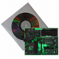
BOARD DEMO FOR MCP215X
Manufacturer
Microchip Technology
Specifications of MCP215XDM
Main Purpose
Interface, IrDA
Embedded
Yes, MCU, 8-Bit
Utilized Ic / Part
MCP2150, MCP2155
Primary Attributes
IrDA Controller with PIC18F MCU
Secondary Attributes
Set up as a Data Logger with LCD, GUI, Socket for EEPROM, Battery Powerable
Processor To Be Evaluated
MCP2150
Silicon Manufacturer
Microchip
Silicon Core Number
MCP2150, MCP2155
Kit Application Type
Interface
Application Sub Type
Standard Protocol Stack Controller
Kit Contents
Board
Rohs Compliant
Yes
Lead Free Status / RoHS Status
Lead free / RoHS Compliant
Lead Free Status / RoHS Status
Lead free / RoHS Compliant, Lead free / RoHS Compliant
Other names
MCP215XDMR
MCP215XDMR
MCP215XDMR
Available stocks
Company
Part Number
Manufacturer
Quantity
Price
Company:

Part Number:
MCP215XDM
Manufacturer:
MICROCHIP
Quantity:
12 000


DS51516B-page 18
2.6.3
There are two PIC16F877A firmware programs that can be demonstrated on the demo
board. These are:
• A vending machine that allows the uploading of data and responds to the
• A 250-byte secondary device (S) to primary device (P) data transfer. This
The 250-byte Secondary device (S) to Primary device (P) data transfer program has
two options. These are:
1. Transfer data from the Host Controller (PIC16F877A) to the MCP2150 while the
2. Transfer 64 bytes of data from the Host Controller (PIC16F877A) to the
Option 2 will demonstrate higher S → P data throughput.
Typical Primary devices include Palm or Pocket PC PDAs and laptop PCs with an IrDA
standard infrared port. The embedded system acts as an IrDA standard Secondary
device.
The PIC16F877A firmware follows the flow control of the host UART interface. These
are the signals between a Host Controller and a MCP2150 device.
The details of the vending machine firmware operation are discussed in
Section 2.6.3.1 “Vending Machine Program Description”.
The details of the “250 byte Secondary Device (S) to Primary Device (P) Data Transfer”
firmware operation are discussed in Section 2.6.3.2 “250-byte Secondary Device (S)
to Primary Device Data Transfer Program Description”.
Figure 2-6
The MCP215X/40 Data Logger Demo Board LCD module will display information on
the state of the firmware execution. This information includes queries for user input.
The selection of the program is dependant on the switches (SW2 and SW3) that are
depressed (see
TABLE 2-2:
The MCP2150/MCP2155/MCP2140 source code of the MCP215X/40 Data Logger
Demo Board is available for download from the Microchip web site at www.micro-
chip.com. This board also supports the MCP2155 device with only a change of the
PIC16F877A firmware. The MCP2140 can be supported with some hardware
modifications (jumper settings) and changes to the PIC16F877A firmware.
SW3 SW2 Demo Program
commands of the Primary device
demonstrates the S → P data throughput
—
—
D
D
Note:
Note:
CTS signal is low.
MCP2150 after CTS signal falling edge.
—
—
D
D
The Embedded System Firmware Overview
shows the program flow that occurs to select between these two programs.
D = Depressed
Rev 2 of the MCP215X/40 Data Logger Demo Board uses firmware revision
1.20 (or later).
N/A
(waiting for a switch to be depressed)
Vending machine
Not implemented
S→P Transfer 250-bytes from demo board to Primary device (PDA)
Figure
DEMO PROGRAM SELECTION
2-4).
— = Not depressed
© 2006 Microchip Technology Inc.
Related parts for MCP215XDM
Image
Part Number
Description
Manufacturer
Datasheet
Request
R

Part Number:
Description:
Manufacturer:
Microchip Technology Inc.
Datasheet:
Part Number:
Description:
Manufacturer:
Microchip Technology Inc.
Datasheet:
Part Number:
Description:
Manufacturer:
Microchip Technology Inc.
Datasheet:
Part Number:
Description:
Manufacturer:
Microchip Technology Inc.
Datasheet:
Part Number:
Description:
Manufacturer:
Microchip Technology Inc.
Datasheet:
Part Number:
Description:
Manufacturer:
Microchip Technology Inc.
Datasheet:
Part Number:
Description:
Manufacturer:
Microchip Technology Inc.
Datasheet:
Part Number:
Description:
Manufacturer:
Microchip Technology Inc.
Datasheet: