MCP215XDM Microchip Technology, MCP215XDM Datasheet - Page 33
MCP215XDM
Manufacturer Part Number
MCP215XDM
Description
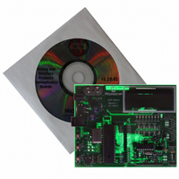
BOARD DEMO FOR MCP215X
Manufacturer
Microchip Technology
Specifications of MCP215XDM
Main Purpose
Interface, IrDA
Embedded
Yes, MCU, 8-Bit
Utilized Ic / Part
MCP2150, MCP2155
Primary Attributes
IrDA Controller with PIC18F MCU
Secondary Attributes
Set up as a Data Logger with LCD, GUI, Socket for EEPROM, Battery Powerable
Processor To Be Evaluated
MCP2150
Silicon Manufacturer
Microchip
Silicon Core Number
MCP2150, MCP2155
Kit Application Type
Interface
Application Sub Type
Standard Protocol Stack Controller
Kit Contents
Board
Rohs Compliant
Yes
Lead Free Status / RoHS Status
Lead free / RoHS Compliant
Lead Free Status / RoHS Status
Lead free / RoHS Compliant, Lead free / RoHS Compliant
Other names
MCP215XDMR
MCP215XDMR
MCP215XDMR
Available stocks
Company
Part Number
Manufacturer
Quantity
Price
Company:

Part Number:
MCP215XDM
Manufacturer:
MICROCHIP
Quantity:
12 000


TABLE 2-5:
© 2006 Microchip Technology Inc.
1
2
3
4
5
6
7
8
9
Step Action
Place both devices on a flat surface about 25 cm (10”)
apart, with the IR ports facing each other.
On the MCP215X/40 Data Logger Demo Board:
Ensure that jumpers are configured as in
On the MCP215X/40 Data Logger Demo Board:
Insert the 9V battery into the battery holder (BT1) or
plug a 9V AC-to-DC power supply (such as those
supplied with some Microchip development tools) into
the 9V DC connection plug (J2).
You may need to depress the RESET switch if the
LCD does not display the Microchip program revision
information, followed by the directions for demo
program selection.
On the MCP215X/40 Data Logger Demo Board:
Depress Switch 2 and Switch 3 (SW2 + SW3)
simultaneously.
On the PDA:
Tap on the MCP215XDemo icon.
On the PDA:
Tap on the Connect button.
On the PDA:
Tap on the 123 button.
On the PDA:
Tap on the number (5) button.
On the PDA:
Tap on the Done button.
250-BYTE S → P DATA TRANSFER DEMO - PALM™ PDA
2.7.1.2.2
The 250-byte S → P data transfer demo is shown by following the steps in
Table
2-5.
Steps to Operate the 250-byte S −− > P Data Transfer Demo
Figure
2-5.
Result
—
—
On the MCP215X/40 Data Logger Demo Board:
The green power LED (D10) will turn on, the DTR LED
will be on, while all the other UART flow control
signals (CTS, RTS, CD, RI and DSR) will be off. The
RD7, RD6, and RD5 LEDs will also be on.
The LCD will display the firmwave Revision
information and then the firmware program selections.
On the MCP215X/40 Data Logger Demo Board:
This causes the 250-byte S
to be executed.
The LCD will display that this program was selected
and then update the display to show the two options
for transmitting data from the PIC16F877A to the
MCP2150:
1.
2.
On the PDA:
The screen will display the MCP215XDemo program
window.
On the PDA:
The Connect button will change to the Disconnect
button.
On the PDA:
This opens the numeric keyboard.
On the PDA:
In the upper-left corner of the window, the typed
number will appear.
On the PDA:
This closes the numeric keyboard window. The
number that was typed is shown on the
“TX Data (ASCII) =” line.
CTS (transmit data bytes while CTS is low)
64 bytes (transmit 64 data bytes when CTS
goes low)
→
P data transfer program
DS51516B-page 29
Related parts for MCP215XDM
Image
Part Number
Description
Manufacturer
Datasheet
Request
R

Part Number:
Description:
Manufacturer:
Microchip Technology Inc.
Datasheet:
Part Number:
Description:
Manufacturer:
Microchip Technology Inc.
Datasheet:
Part Number:
Description:
Manufacturer:
Microchip Technology Inc.
Datasheet:
Part Number:
Description:
Manufacturer:
Microchip Technology Inc.
Datasheet:
Part Number:
Description:
Manufacturer:
Microchip Technology Inc.
Datasheet:
Part Number:
Description:
Manufacturer:
Microchip Technology Inc.
Datasheet:
Part Number:
Description:
Manufacturer:
Microchip Technology Inc.
Datasheet:
Part Number:
Description:
Manufacturer:
Microchip Technology Inc.
Datasheet: