MCP215XDM Microchip Technology, MCP215XDM Datasheet - Page 49
MCP215XDM
Manufacturer Part Number
MCP215XDM
Description
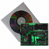
BOARD DEMO FOR MCP215X
Manufacturer
Microchip Technology
Specifications of MCP215XDM
Main Purpose
Interface, IrDA
Embedded
Yes, MCU, 8-Bit
Utilized Ic / Part
MCP2150, MCP2155
Primary Attributes
IrDA Controller with PIC18F MCU
Secondary Attributes
Set up as a Data Logger with LCD, GUI, Socket for EEPROM, Battery Powerable
Processor To Be Evaluated
MCP2150
Silicon Manufacturer
Microchip
Silicon Core Number
MCP2150, MCP2155
Kit Application Type
Interface
Application Sub Type
Standard Protocol Stack Controller
Kit Contents
Board
Rohs Compliant
Yes
Lead Free Status / RoHS Status
Lead free / RoHS Compliant
Lead Free Status / RoHS Status
Lead free / RoHS Compliant, Lead free / RoHS Compliant
Other names
MCP215XDMR
MCP215XDMR
MCP215XDMR
Available stocks
Company
Part Number
Manufacturer
Quantity
Price
Company:

Part Number:
MCP215XDM
Manufacturer:
MICROCHIP
Quantity:
12 000


© 2006 Microchip Technology Inc.
2.8.3
The MCP215X interfaces to the PIC16F877A (or PIC16F877AA) microcontroller (U1).
This device was chosen for this application because it has a UART port, an A/D
Converter (ADC), Flash memory for reprogrammability, a sufficient number of I/O pins
to interface to the LED and LCD module and is low power.
The MCLR input of the PIC16F877A is connected to the RESET push button switch.
The device is reset when the RESET push button is depressed.
The PIC16F877A RA5 pin is connected to the S2 push button switch, while the RA4
pin is connected to the S3 push button switch. After device reset, the state of these
switches is polled to determine which firmware program (vending machine or 250-byte
S → P data transmit) to execute.
The PIC16F877A is connected to a standard In-Circuit Serial Programming™ (ICSP™)
header (J3) to allow easy program access to the device.
2.8.4
The IR transceiver circuit uses a Vishay
Footprints are preset for populating a circuit using the Vishay TDFU 4100 or the Agilent
HSDL-3000. Jumpers are present so that after these optional circuits have been imple-
mented, the selection of the desired circuit is easy.
2.8.5
The MCP111 is used to force the MCP215X devices into the reset state when the reg-
ulated system voltage falls below the minimum expected voltage.
2.8.6
To allow easy access to many of the system signals, a header (J14) was placed on one
of the edges of the board. This allows the signals from the MCP2150, MCP2155, or
MCP2140 to be accessed.
FIGURE 2-13:
Note:
PIC
IR Transceiver Circuit
Voltage Supervisor
Signal Header
If either option circuit is implemented, ensure to cut (open) the trace jumper
shorting both terminals of JP1C1 and JP2C1.
®
Microcontroller Functions
SIGNAL INTERFACE HEADER J14
J4
®
TFDU 4300 integrated optical transceiver.
DS51516B-page 45
Related parts for MCP215XDM
Image
Part Number
Description
Manufacturer
Datasheet
Request
R

Part Number:
Description:
Manufacturer:
Microchip Technology Inc.
Datasheet:
Part Number:
Description:
Manufacturer:
Microchip Technology Inc.
Datasheet:
Part Number:
Description:
Manufacturer:
Microchip Technology Inc.
Datasheet:
Part Number:
Description:
Manufacturer:
Microchip Technology Inc.
Datasheet:
Part Number:
Description:
Manufacturer:
Microchip Technology Inc.
Datasheet:
Part Number:
Description:
Manufacturer:
Microchip Technology Inc.
Datasheet:
Part Number:
Description:
Manufacturer:
Microchip Technology Inc.
Datasheet:
Part Number:
Description:
Manufacturer:
Microchip Technology Inc.
Datasheet: