MCP215XDM Microchip Technology, MCP215XDM Datasheet - Page 15
MCP215XDM
Manufacturer Part Number
MCP215XDM
Description
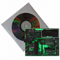
BOARD DEMO FOR MCP215X
Manufacturer
Microchip Technology
Specifications of MCP215XDM
Main Purpose
Interface, IrDA
Embedded
Yes, MCU, 8-Bit
Utilized Ic / Part
MCP2150, MCP2155
Primary Attributes
IrDA Controller with PIC18F MCU
Secondary Attributes
Set up as a Data Logger with LCD, GUI, Socket for EEPROM, Battery Powerable
Processor To Be Evaluated
MCP2150
Silicon Manufacturer
Microchip
Silicon Core Number
MCP2150, MCP2155
Kit Application Type
Interface
Application Sub Type
Standard Protocol Stack Controller
Kit Contents
Board
Rohs Compliant
Yes
Lead Free Status / RoHS Status
Lead free / RoHS Compliant
Lead Free Status / RoHS Status
Lead free / RoHS Compliant, Lead free / RoHS Compliant
Other names
MCP215XDMR
MCP215XDMR
MCP215XDMR
Available stocks
Company
Part Number
Manufacturer
Quantity
Price
Company:

Part Number:
MCP215XDM
Manufacturer:
MICROCHIP
Quantity:
12 000


2.6
© 2006 Microchip Technology Inc.
GETTING STARTED
This section presents an overview of the following system blocks:
• The MCP215X/40 Data Logger Demo Board Hardware
• The MCP215X/40 Data Logger Demo Board Firmware
• The Primary device Graphical User Interface (GUI)
This should give you an understanding of what these components do in the complete
IrDA standard system.
2.6.1
The major components for the MCP215X/40 Data Logger Demo Board are:
1. DIP Socket (U7) for either MCP2150, MCP2155, or MCP2140 device
2. MCP2150 Device (inserted in U7)
3. Optical transceiver (U14 - TFDU 4300),
4. MCP2140 optical transceiver output wave shaping circuit
5. PIC MCU (U1 - PIC16F877A)
6. LCD module
7. Power supply
8. Voltage Supervisor (VS1)
9. User inputs to PIC MCU (SW2, SW3 and variable resistor (VR1))
10. PIC MCU RESET (SW1)
11. PIC MCU crystal (Y2)
The MCP215X/40 Data Logger Demo Board is fully assembled and tested for evalua-
tion and demonstration of the MCP2150 features. The MCP2155 or MCP2140 devices
are not tested.
Figure 2-1
tion to points of interest.
For more detailed circuit information, refer to Appendix A. “Schematics and Lay-
outs” and Appendix B. “Bill Of Materials (BOM)”.
optional optical transceiver circuits include footprints for TFDU 4100 (U13) and
HSDL 3000 (U12)
The MCP215X/40 Data Logger Demo Board Hardware Overview
shows the layout of the MCP215X/40 Data Logger Demo Board with indica-
DS51516B-page 11
Related parts for MCP215XDM
Image
Part Number
Description
Manufacturer
Datasheet
Request
R

Part Number:
Description:
Manufacturer:
Microchip Technology Inc.
Datasheet:
Part Number:
Description:
Manufacturer:
Microchip Technology Inc.
Datasheet:
Part Number:
Description:
Manufacturer:
Microchip Technology Inc.
Datasheet:
Part Number:
Description:
Manufacturer:
Microchip Technology Inc.
Datasheet:
Part Number:
Description:
Manufacturer:
Microchip Technology Inc.
Datasheet:
Part Number:
Description:
Manufacturer:
Microchip Technology Inc.
Datasheet:
Part Number:
Description:
Manufacturer:
Microchip Technology Inc.
Datasheet:
Part Number:
Description:
Manufacturer:
Microchip Technology Inc.
Datasheet: