MCP212XEV-DB Microchip Technology, MCP212XEV-DB Datasheet - Page 43
MCP212XEV-DB
Manufacturer Part Number
MCP212XEV-DB
Description
BOARD DEMO FOR MCP212X
Manufacturer
Microchip Technology
Specifications of MCP212XEV-DB
Main Purpose
Interface, Infrared Transceiver
Utilized Ic / Part
MCP2120, MCP2122
Processor To Be Evaluated
MCP2122 and MCP2120
Interface Type
UART
Silicon Manufacturer
Microchip
Silicon Core Number
MCP2120, MCP2122
Kit Contents
MCP2122 Daughter Board, Docs
Features
8-Pin And 14-Pin Sockets, Three Optical Transceiver Circuits
Mcu Supported Families
MCP212x
Rohs Compliant
Yes
Lead Free Status / RoHS Status
Contains lead / RoHS non-compliant
Secondary Attributes
-
Embedded
-
Primary Attributes
-
Lead Free Status / Rohs Status
Lead free / RoHS Compliant
Available stocks
Company
Part Number
Manufacturer
Quantity
Price
Company:

Part Number:
MCP212XEV-DB
Manufacturer:
MICROCHIP
Quantity:
12 000


FIGURE E-2:
TABLE E-3:
© 2006 Microchip Technology Inc.
1
Step Action
Place both devices on a flat surface about 25 cm (10”)
apart, with the IR ports facing each other.
DEMO #1 TEST STEPS
E.1.1
In Demo #1, the System 2 unit will echo any alpha character received, changing the
case of the character (lowercase to uppercase/uppercase to lowercase). The System
1 unit is connected to the PC, while the System 2 unit is not connected, though it still
needs to be powered. The PICDEM™ FS USB Demo Board is used to determine the
communication baud rate (9600) via the JP3, JP2 and JP1 jumper states. Given this
state, the PICmicro
Power is supplied over the J3 interface header. Jumper JP4 is used to select which
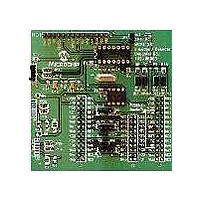
demo program to run. Figure E-2 shows the jumper configuration for Demo #1.
Table E-3 shows the steps for Demo #1.
DEMO #1 CONFIGURATION
Demo #1 Operation
Using the MCP212X Developer’s Daughter Board
®
MCU can then supply the 16XCLK frequency to the MCP2122.
with the PICDEM™ FS USB Demo Board
Result
—
DS51571B-page 39
Related parts for MCP212XEV-DB
Image
Part Number
Description
Manufacturer
Datasheet
Request
R

Part Number:
Description:
Manufacturer:
Microchip Technology Inc.
Datasheet:
Part Number:
Description:
Manufacturer:
Microchip Technology Inc.
Datasheet:
Part Number:
Description:
Manufacturer:
Microchip Technology Inc.
Datasheet:
Part Number:
Description:
Manufacturer:
Microchip Technology Inc.
Datasheet:
Part Number:
Description:
Manufacturer:
Microchip Technology Inc.
Datasheet:
Part Number:
Description:
Manufacturer:
Microchip Technology Inc.
Datasheet:
Part Number:
Description:
Manufacturer:
Microchip Technology Inc.
Datasheet:
Part Number:
Description:
Manufacturer:
Microchip Technology Inc.
Datasheet: