MCP212XEV-DB Microchip Technology, MCP212XEV-DB Datasheet - Page 38
MCP212XEV-DB
Manufacturer Part Number
MCP212XEV-DB
Description
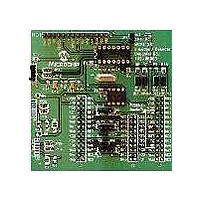
BOARD DEMO FOR MCP212X
Manufacturer
Microchip Technology
Specifications of MCP212XEV-DB
Main Purpose
Interface, Infrared Transceiver
Utilized Ic / Part
MCP2120, MCP2122
Processor To Be Evaluated
MCP2122 and MCP2120
Interface Type
UART
Silicon Manufacturer
Microchip
Silicon Core Number
MCP2120, MCP2122
Kit Contents
MCP2122 Daughter Board, Docs
Features
8-Pin And 14-Pin Sockets, Three Optical Transceiver Circuits
Mcu Supported Families
MCP212x
Rohs Compliant
Yes
Lead Free Status / RoHS Status
Contains lead / RoHS non-compliant
Secondary Attributes
-
Embedded
-
Primary Attributes
-
Lead Free Status / Rohs Status
Lead free / RoHS Compliant
Available stocks
Company
Part Number
Manufacturer
Quantity
Price
Company:

Part Number:
MCP212XEV-DB
Manufacturer:
MICROCHIP
Quantity:
12 000


TABLE D-3:
DS51571B-page 34
1
2
3
4
5
6
7
8
9
10
11
12
13
14
Step Action
Place both devices on a flat surface about 25 cm (10”)
apart, with the IR ports facing each other.
On the System #1 Unit:
The jumpers must be configured as in Figure D-3.
On the System #1 Unit:
Apply power to the unit via the 9V power supply.
On the System #1 Unit:
Connect the PC serial port cable that is connected to
COM1.
On the System #2 Unit:
Insert the MCP212X Developer’s Daughter Board into
the PICDEM™ HPC Explorer Demo Board.
Ensure that the jumpers are configured as in
Figure D-2.
On the System #2 Unit:
Apply power to the unit via the 9V power supply.
On the System #2 Unit:
Connect the PC serial port cable that is connected to
COM2.
On the System #1 Unit:
Depress and release Switch 2 (S2 – MCLR).
On the System #2 Unit:
Depress and release Switch 2 (S2 – MCLR).
On the PC:
Open the HyperTerminal
COM 1.
Ensure that the window indicates that the
HyperTerminal program is connected.
On the PC:
In the HyperTerminal program COM1 window, type
alpha-numeric characters (such as “123456 asdfg”).
On the PC:
In the HyperTerminal program COM2 window, depress
the Return key and type alpha-numeric characters
(such as “7890 hjkl;”).
On the System #2 Unit:
Power-down the board and remove the tested
MCP212x Daughter Board.
Go to Step #5
DEMO #1 STEPS
Table D-3 shows the steps for Demo #1 operation.
®
program window for
Result
—
—
On the System #1 Unit:
The green power LED (D) will turn on.
—
Test unit will echo the received Alpha character
(changing the case; upper to lower and lower to
upper).
On the System #2 Unit:
The green power LED (D) will turn on.
—
—
—
—
On the PC:
In the HyperTerminal program COM 2 window, the
same characters should be displayed (“123456
asdfg”).
On the PC:
In the HyperTerminal program COM 1 window, the
same characters should be displayed (“7890 hjkl;”) on
the line below the “123456 asdfg” characters.
—
—
© 2006 Microchip Technology Inc.
Related parts for MCP212XEV-DB
Image
Part Number
Description
Manufacturer
Datasheet
Request
R

Part Number:
Description:
Manufacturer:
Microchip Technology Inc.
Datasheet:
Part Number:
Description:
Manufacturer:
Microchip Technology Inc.
Datasheet:
Part Number:
Description:
Manufacturer:
Microchip Technology Inc.
Datasheet:
Part Number:
Description:
Manufacturer:
Microchip Technology Inc.
Datasheet:
Part Number:
Description:
Manufacturer:
Microchip Technology Inc.
Datasheet:
Part Number:
Description:
Manufacturer:
Microchip Technology Inc.
Datasheet:
Part Number:
Description:
Manufacturer:
Microchip Technology Inc.
Datasheet:
Part Number:
Description:
Manufacturer:
Microchip Technology Inc.
Datasheet: