MCP212XEV-DB Microchip Technology, MCP212XEV-DB Datasheet - Page 22
MCP212XEV-DB
Manufacturer Part Number
MCP212XEV-DB
Description
BOARD DEMO FOR MCP212X
Manufacturer
Microchip Technology
Specifications of MCP212XEV-DB
Main Purpose
Interface, Infrared Transceiver
Utilized Ic / Part
MCP2120, MCP2122
Processor To Be Evaluated
MCP2122 and MCP2120
Interface Type
UART
Silicon Manufacturer
Microchip
Silicon Core Number
MCP2120, MCP2122
Kit Contents
MCP2122 Daughter Board, Docs
Features
8-Pin And 14-Pin Sockets, Three Optical Transceiver Circuits
Mcu Supported Families
MCP212x
Rohs Compliant
Yes
Lead Free Status / RoHS Status
Contains lead / RoHS non-compliant
Secondary Attributes
-
Embedded
-
Primary Attributes
-
Lead Free Status / Rohs Status
Lead free / RoHS Compliant
Available stocks
Company
Part Number
Manufacturer
Quantity
Price
Company:

Part Number:
MCP212XEV-DB
Manufacturer:
MICROCHIP
Quantity:
12 000


2.5
DS51571B-page 18
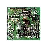
MCP212X DEVELOPER’S DAUGHTER BOARD DESCRIPTION
The following sections describe each element of this daughter board in further detail.
2.5.1
The MCP212X Developer’s Daughter Board is powered by a 5V supply. This voltage
supply may be sourced via the PCB headers.
When the device is used in conjunction with the appropriate PICDEM™ Demo Board,
the power is supplied via the connector interface. If the MCP212X Developer’s
Daughter Board is jumpered into an application circuit via the HD1 connector, the
device power supply must be brought over as well.
2.5.2
This demo board highlights the MCP2122 device (U4) and MCP2120 device (U1) to
demonstrate the implementation of an IR port in an embedded system application. The
MCP2120 device handles the encoding/decoding of the UART/IR bit stream.
Further Host Controller interface information is available in the device documentation:
• MCP2122 Data Sheet, “Infrared Encoder/Decoder” (DS21894)
• MCP2120 Data Sheet, “Infrared Encoder/Decoder” (DS21618)
• AN946, “Interfacing the MCP2122 to the Host Controller” (DS00946)
2.5.2.1
The MCP2122 (U4) implements an IrDA standard encoder/decoder. The baud rate is
determined by the frequency of the 16XCLK input.
The key signals for the MCP2122-to-microcontroller (Host UART) interface are shown
in Table 2-4. The key signals for the MCP2122-to-IR transceiver circuit are shown in
Table 2-5.
TABLE 2-4:
TABLE 2-5:
TXIR
RXIR
Legend: A = Analog
In addition to the signals described in Table 2-4 and Table 2-5, the MCP2120 RESET
input is connected to the RESET output of the Host Controller.
TX
RX
16XCLK
Legend: TTL = TTL compatible input
Pin Name
Name
Pin
I = Input
I = Input
Power
MCP212X IrDA
MCP2122 OPERATION
Number
Number
(PDIP)
(PDIP)
Pin
Pin
MCP2122 HOST UART INTERFACE PINS
MCP2122 IR INTERFACE PINS
2
3
2
3
1
Type
Type
Pin
Pin
O
O
P = Power
O = Output
I
I
I
®
Standard Encoder/Decoder Device
Buffer
Buffer
Type
Type
TTL
TTL
ST
—
—
Asynchronous transmit to IrDA
transceiver
Asynchronous receive from infrared transceiver
ST = Schmitt Trigger input with CMOS levels
O = Output
Asynchronous receive; from Host Controller UART
Asynchronous transmit; to Host Controller UART
16 x Clock
Description
Description
© 2006 Microchip Technology Inc.
®
standard
Related parts for MCP212XEV-DB
Image
Part Number
Description
Manufacturer
Datasheet
Request
R

Part Number:
Description:
Manufacturer:
Microchip Technology Inc.
Datasheet:
Part Number:
Description:
Manufacturer:
Microchip Technology Inc.
Datasheet:
Part Number:
Description:
Manufacturer:
Microchip Technology Inc.
Datasheet:
Part Number:
Description:
Manufacturer:
Microchip Technology Inc.
Datasheet:
Part Number:
Description:
Manufacturer:
Microchip Technology Inc.
Datasheet:
Part Number:
Description:
Manufacturer:
Microchip Technology Inc.
Datasheet:
Part Number:
Description:
Manufacturer:
Microchip Technology Inc.
Datasheet:
Part Number:
Description:
Manufacturer:
Microchip Technology Inc.
Datasheet: