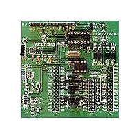
MCP212XEV-DB Microchip Technology, MCP212XEV-DB Datasheet - Page 20

MCP212XEV-DB
Manufacturer Part Number
MCP212XEV-DB
Description
BOARD DEMO FOR MCP212X
Manufacturer
Microchip Technology
Specifications of MCP212XEV-DB
Main Purpose
Interface, Infrared Transceiver
Utilized Ic / Part
MCP2120, MCP2122
Processor To Be Evaluated
MCP2122 and MCP2120
Interface Type
UART
Silicon Manufacturer
Microchip
Silicon Core Number
MCP2120, MCP2122
Kit Contents
MCP2122 Daughter Board, Docs
Features
8-Pin And 14-Pin Sockets, Three Optical Transceiver Circuits
Mcu Supported Families
MCP212x
Rohs Compliant
Yes
Lead Free Status / RoHS Status
Contains lead / RoHS non-compliant
Secondary Attributes
-
Embedded
-
Primary Attributes
-
Lead Free Status / Rohs Status
Lead free / RoHS Compliant
Available stocks
Company
Part Number
Manufacturer
Quantity
Price
Company:
Part Number:
MCP212XEV-DB
Manufacturer:
MICROCHIP
Quantity:
12 000
2.4
DS51571B-page 16
Qty
1
2
2
2
2
PC with 2 serial ports
Serial Cables
PICDEM™ HPC Explorer Boards The MCP212X Developer’s Daughter Board will be installed into this board
MCP2120 Daughter Boards
2 PICDEM™ HPC Explorer Demo
Board Power Supplies (9V DC)
MAKING A DEMO SYSTEM
Hardware
The MCP212X Developer’s Daughter Board requires a clock source and either a Host
Controller or a UART circuit. To demonstrate the board, the easiest method is to use
one of the compatible PICDEM™ Demo Boards. A good choice is the PICDEM™ HPC
Explorer Demo Board. This allows the MCP2120 device to interface to either:
• PIC18F8722’s EUSART1
• PIC18F8722’s EUSART2
• PICDEM™ HPC Explorer Demo Board’s DB-9 connector (MAX3232C)
Additional instructions for performing a demo using the PICDEM™ HPC Explorer
Demo Board are shown in Appendix D. “Using the MCP212X Developer’s Daughter
Board with the PICDEM™ HPC Explorer Demo Board”. Appendix E. “Using the
MCP212X Developer’s Daughter Board with the PICDEM™ FS USB Demo Board”
supplies instructions for performing a demo using the PICDEM™ FS USB Demo
Board. Appendix F. “Configuring the HyperTerminal
configuring the HyperTerminal program on the PC.
System Requirements
Table 2-3 shows the requirements for a system that can be used to demonstrate the
MCP212X Developer’s Daughter Board.
System Setup
The system setup requires a PC with two serial communication ports (UARTs) and
HyperTerminal, the system application program. Two PICDEM™ HPC Explorer Demo
Boards and two MCP212X Daughter Boards are then needed.
Figure 2-4 shows a system block diagram.
TABLE 2-3:
Note:
The MCP2122 may be installed in U4, or the MCP2120 may be installed in
U1. However, these devices should not be installed at the same time.
SYSTEM HARDWARE REQUIREMENTS
Purpose
The PC will “talk” to each PICDEM™ HPC Explorer Demo Board
(Encoder/Decoder board) via the serial port and an instance of the
HyperTerminal
“System #1” PICDEM™ HPC Explorer Demo Board. Com 2 will be used to
communicate to the “System #2” PICDEM™ HPC Explorer Demo Board.
To connect the PC serial ports to each PICDEM™ HPC Explorer Demo
Board’s serial port.
for testing.
This board will be used to communicate with the system under test.
Used to power each of the PICDEM™ HPC Explorer Demo Boards.
®
program. For consistency, COM 1 will be used to talk to the
®
Program” may be useful for
© 2006 Microchip Technology Inc.


