MCP212XEV-DB Microchip Technology, MCP212XEV-DB Datasheet - Page 18
MCP212XEV-DB
Manufacturer Part Number
MCP212XEV-DB
Description
BOARD DEMO FOR MCP212X
Manufacturer
Microchip Technology
Specifications of MCP212XEV-DB
Main Purpose
Interface, Infrared Transceiver
Utilized Ic / Part
MCP2120, MCP2122
Processor To Be Evaluated
MCP2122 and MCP2120
Interface Type
UART
Silicon Manufacturer
Microchip
Silicon Core Number
MCP2120, MCP2122
Kit Contents
MCP2122 Daughter Board, Docs
Features
8-Pin And 14-Pin Sockets, Three Optical Transceiver Circuits
Mcu Supported Families
MCP212x
Rohs Compliant
Yes
Lead Free Status / RoHS Status
Contains lead / RoHS non-compliant
Secondary Attributes
-
Embedded
-
Primary Attributes
-
Lead Free Status / Rohs Status
Lead free / RoHS Compliant
Available stocks
Company
Part Number
Manufacturer
Quantity
Price
Company:

Part Number:
MCP212XEV-DB
Manufacturer:
MICROCHIP
Quantity:
12 000


FIGURE 2-3:
DS51571B-page 14
Baud Rate Selection
JP1 JP2 JP3
9600 Baud
19200 Baud
38400 Baud
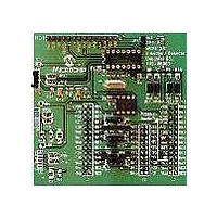
Figure 2-3 shows the component layout for the MCP212X Developer’s Daughter Board
and the operation of the JP1, JP2, JP3 and JP4 jumpers. When the jumper is open, the
signal is pulled high. When the jumper is shorted, the signal is pulled to ground. JP1 is
connected to the header’s RA0 signal, JP2 is connected to the header’s RA1 signal,
JP3 is connected to the header’s RC0 signal and JP4 is connected to the header’s RC1
signal. These signals are also connected to the MCP2120’s BAUD and MODE pins.
JP1, JP2, JP3 AND JP4 CONFIGURATIONS
Settings
All Other
115200 Baud
Not Defined
57600 Baud
Note 1:
Mode Selection
This is the firmware operation for
00063 HPC.asm when used w/
the PICDEM™ HPC Explorer
Demo Board.
MCP212X communicates with
DB-9 (PC)
MCP212X communicates with
PIC18F8722
© 2006 Microchip Technology Inc.
(1)
Related parts for MCP212XEV-DB
Image
Part Number
Description
Manufacturer
Datasheet
Request
R

Part Number:
Description:
Manufacturer:
Microchip Technology Inc.
Datasheet:
Part Number:
Description:
Manufacturer:
Microchip Technology Inc.
Datasheet:
Part Number:
Description:
Manufacturer:
Microchip Technology Inc.
Datasheet:
Part Number:
Description:
Manufacturer:
Microchip Technology Inc.
Datasheet:
Part Number:
Description:
Manufacturer:
Microchip Technology Inc.
Datasheet:
Part Number:
Description:
Manufacturer:
Microchip Technology Inc.
Datasheet:
Part Number:
Description:
Manufacturer:
Microchip Technology Inc.
Datasheet:
Part Number:
Description:
Manufacturer:
Microchip Technology Inc.
Datasheet: