AD9516-1/PCBZ Analog Devices Inc, AD9516-1/PCBZ Datasheet - Page 60
AD9516-1/PCBZ
Manufacturer Part Number
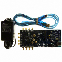
AD9516-1/PCBZ
Description
BOARD EVALUATION FOR AD9516-1
Manufacturer
Analog Devices Inc
Specifications of AD9516-1/PCBZ
Main Purpose
Timing, Clock Generator
Embedded
No
Utilized Ic / Part
AD9516-1
Primary Attributes
2 Inputs, 14 Outputs, 2.5GHz VCO
Secondary Attributes
CMOS, LVDS, LVPECL Output Logic, ADIsimCLK™ Graphical User Interface
Silicon Manufacturer
Analog Devices
Application Sub Type
PLL Clock Synthesizer
Kit Application Type
Clock & Timing
Silicon Core Number
AD9516-0, AD9516-1, AD9516-2
Silicon Family Name
AD9516-X
Rohs Compliant
Yes
Lead Free Status / RoHS Status
Lead free / RoHS Compliant


AD9516-1
Table 54. PLL
Reg.
Addr.
(Hex)
0x010
0x011
0x012
0x013
0x014
0x015
0x016
Bits
7
[6:4]
[3:2]
[1:0]
[7:0]
[5:0]
[5:0]
[7:0]
[4:0]
7
6
5
4
3
Name
PFD polarity
CP current
CP mode
PLL power-down
14-bit R divider,
Bits[7:0] (LSB)
14-bit R divider,
Bits[13:8] (MSB)
6-bit A counter
13-bit B counter,
Bits[7:0] (LSB)
13-bit B counter,
Bits[12:8] (MSB)
Set CP pin to V
Reset R counter
Reset A, B counters
Reset all counters
B counter
bypass
CP
/2
Description
Sets the PFD polarity. Negative polarity is for use (if needed) with external VCO/VCXO only. The on-chip VCO requires
positive polarity; Bit 7 = 0.
0: positive; higher control voltage produces higher frequency (default).
1: negative; higher control voltage produces lower frequency.
Charge pump current (with CPRSET = 5.1 kΩ).
6
0
0
0
0
1
1
1
1
Charge pump operating mode.
3
0
0
1
1
PLL operating mode.
1
0
0
1
1
R divider LSBs—lower eight bits (default = 0x01).
R divider MSBs—upper six bits (default = 0x00).
A counter (part of N divider) (default = 0x00).
B counter (part of N divider)—lower eight bits (default = 0x03).
B counter (part of N divider)—upper five bits (default = 0x00).
Sets the CP pin to one-half of the V
0: CP normal operation (default).
1: CP pin set to V
Resets R counter (R divider).
0: normal (default).
1: holds the R counter in reset.
Resets A and B counters (part of N divider).
0: normal (default).
1: holds the A and B counters in reset.
Resets R, A, and B counters.
0: normal (default).
1: holds the R, A, and B counters in reset.
B counter bypass. This is valid only when operating the prescaler in FD mode.
0: normal (default).
1: B counter is set to divide-by-1. This allows the prescaler setting to determine the divide for the N divider.
2
5
0
0
1
1
0
0
1
1
0
1
0
1
0
0
1
0
1
4
0
1
0
1
0
1
0
1
Charge Pump Mode
High impedance state.
Force source current (pump up).
Force sink current (pump down).
Normal operation (default).
Mode
Normal operation.
Asynchronous power-down (default).
Normal operation.
Synchronous power-down.
I
0.6
1.2
1.8
2.4
3.0
3.6
4.2
4.8 (default)
CP
CP
/2.
(mA)
Rev. A | Page 60 of 80
CP
supply voltage.
Related parts for AD9516-1/PCBZ
Image
Part Number
Description
Manufacturer
Datasheet
Request
R

Part Number:
Description:
IC CLOCK PLL/VCO 2GHZ 64LFCSP
Manufacturer:
Analog Devices Inc
Datasheet:
Part Number:
Description:
IC CLOCK GEN 2.8GHZ VCO 64-LFCSP
Manufacturer:
Analog Devices Inc
Datasheet:
Part Number:
Description:
IC,Fourteen Distributed-Output Clock Driver,LLCC,64PIN,PLASTIC
Manufacturer:
Analog Devices Inc
Datasheet:
Part Number:
Description:
IC,Ten Distributed-Output Clock Driver,LLCC,64PIN,PLASTIC
Manufacturer:
Analog Devices Inc
Datasheet:
Part Number:
Description:
IC,Ten Distributed-Output Clock Driver,LLCC,64PIN,PLASTIC
Manufacturer:
Analog Devices Inc
Datasheet:
Part Number:
Description:
Clock IC With 1.8GHz On-chip VCO
Manufacturer:
Analog Devices Inc
Datasheet:

Part Number:
Description:
BOARD EVAL FOR AD9516-3 2.0GHZ
Manufacturer:
Analog Devices Inc
Datasheet:

Part Number:
Description:
BOARD EVAL FOR AD9516-4 1.8GHZ
Manufacturer:
Analog Devices Inc
Datasheet:
Part Number:
Description:
IC,Ten Distributed-Output Clock Driver,LLCC,64PIN,PLASTIC
Manufacturer:
Analog Devices Inc
Datasheet:
Part Number:
Description:
IC,Fourteen Distributed-Output Clock Driver,LLCC,64PIN,PLASTIC
Manufacturer:
Analog Devices Inc
Datasheet:
Part Number:
Description:
IC,Ten Distributed-Output Clock Driver,LLCC,64PIN,PLASTIC
Manufacturer:
Analog Devices Inc
Datasheet:
Part Number:
Description:
Clock IC With 1.8GHz On-chip VCO
Manufacturer:
Analog Devices Inc
Datasheet:
Part Number:
Description:
10/14 Chan Clock IC W/PLL-no VCO
Manufacturer:
Analog Devices Inc
Datasheet:
Part Number:
Description:
10/14 Chan Clock IC W/PLL-no VCO
Manufacturer:
Analog Devices Inc
Datasheet:

Part Number:
Description:
Clock IC With 2.5GHz On-chip VCO EB
Manufacturer:
Analog Devices Inc
Datasheet: