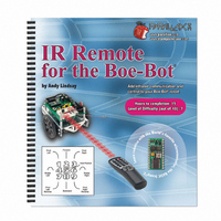
70016 Parallax Inc, 70016 Datasheet - Page 189

70016
Manufacturer Part Number
70016
Description
TEXT INFRARED REMOTE FOR BOE-BOT
Manufacturer
Parallax Inc
Datasheet
1.70016.pdf
(212 pages)
Specifications of 70016
Accessory Type
Manual
Product
Microcontroller Accessories
Lead Free Status / RoHS Status
Contains lead / RoHS non-compliant
For Use With/related Products
Boe-Bot®
For Use With
29122 - KIT PARTS IR REMOTE FOR BOE-BOT
Lead Free Status / RoHS Status
Lead free / RoHS Compliant, Contains lead / RoHS non-compliant
Available stocks
Company
Part Number
Manufacturer
Quantity
Price
- Current page: 189 of 212
- Download datasheet (3Mb)
should be either 1, 4, 8, or 16. For this activity, we'll go with 8, but the number of data
bits can be increased or decreased, simply by changing a couple lines of code. Here is
how the protocol will work:
TransmitCustomIrMessages.bs2 sends its messages as
circuit. The IR LED flashes on/off at 38 kHz for either 3, 2, or 1 ms. If this 38 kHz IR
flashing on/off shines on the IR receiver, it sends low signals while it detects that flashing
IR.
As a result of the flashing IR, the IR receiver will send low signals that last either 3, 2, or
1 ms.
ReceiveCustomIrMessages.bs2, measures these low signals with the
It then decodes these durations, storing the result as binary bits in a variable.
Testing IR Communication
TransmitCustomIrMessage.bs2 has some extra code in it that causes it to send a different
letter of the alphabet each time the Reset button on the board is pressed and released.
The sequence it will transmit is "a", "b", "c", ... "z". This program should be downloaded
to the BASIC Stamp on the board with the transmit circuit. This board can then be
disconnected from the serial cable. Then, the board with the receiver circuit can be
connected
ReceiveCustomIrMessages.bs2. After pointing the top of the IR LED at the face of the
IR receiver (see Figure B-1), each time the transmit board's Reset button is pressed and
released, the receiver board should display the character that was received and decoded in
the Debug Terminal.
•
•
•
•
•
•
•
√
√
Pulses transmitted are least significant bit (LSB) first.
8 data bits are transmitted
A start bit is 3 ms
A binary-1 is 2 ms
A binary-0 is 1 ms
The minimum delay between pulses is at least 1 ms + any loop processing
overhead on the transmitter side.
The maximum delay between pulses is 0.131 s.
Connect the board with the IR transmitting circuit shown in Figure B-1 to the
Programming cable.
Download TransmitCustomIrMessage.bs2 to the transmitting BS2.
The BASIC Stamp module on the receiving end, which runs
(and
left
connected)
to
the
FREQOUT
serial
cable
commands to an IR LED
PULSIN
while
command.
running
Related parts for 70016
Image
Part Number
Description
Manufacturer
Datasheet
Request
R

Part Number:
Description:
Microcontroller Modules & Accessories Breadboard Set
Manufacturer:
Parallax Inc

Part Number:
Description:
Power Entry Modules 4AA Battery Holder
Manufacturer:
Parallax Inc

Part Number:
Description:
Microcontroller Modules & Accessories DISCONTINUED BY PARALLAX
Manufacturer:
Parallax Inc

Part Number:
Description:
BOOK UNDERSTANDING SIGNALS
Manufacturer:
Parallax Inc
Datasheet:

Part Number:
Description:
COMPETITION RING FOR SUMOBOT
Manufacturer:
Parallax Inc
Datasheet:

Part Number:
Description:
Microcontroller Modules & Accessories DISCONTINUED BY PARALLAX
Manufacturer:
Parallax Inc

Part Number:
Description:
BOOK UNDERSTANDING SIGNALS
Manufacturer:
Parallax Inc
Datasheet:

Part Number:
Description:
BOARD EXPERIMENT+LCD NX-1000
Manufacturer:
Parallax Inc
Datasheet:

Part Number:
Description:
IC MCU 2K FLASH 50MHZ SO-18
Manufacturer:
Parallax Inc
Datasheet:


