LZSA-1000-3 TDK Corporation, LZSA-1000-3 Datasheet - Page 9
LZSA-1000-3
Manufacturer Part Number
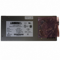
LZSA-1000-3
Description
PWR SUP 24V 1008W 42A
Manufacturer
TDK Corporation
Series
LZSAr
Type
Industrialr
Specifications of LZSA-1000-3
Power Supply Type
Switching (Closed Frame)
Voltage - Output
24V
Number Of Outputs
1
Power (watts)
1000W
Applications
Commercial
Voltage - Input
85 ~ 265VAC
Mounting Type
Chassis Mount
1st Output
24 VDC @ 42 A
Size / Dimension
10.5" L x 5.62" W x 4.75" H (266.7mm x 142.7mm x 120.7mm)
Power (watts) - Rated
1008W
Operating Temperature
-40°C ~ 71°C
Efficiency
84%
Approvals
CE, EN, UL
Line Regulation
0.1%
Load Regulation
0.1%
Power Supply Output Type
Fixed
No. Of Outputs
1
Output Voltage
24V
Output Current
42A
Power Rating
1008W
Input Voltage
85V AC To 265V AC / 100V DC To 400V DC
Brand/series
LZSA Series
Configuration
Enclosed
Operation
Linear
Output
24 VDC @ 42 A
Power, Output
1008 W
Primary Type
AC-DC
Special Features
High Reliability, Parallelable, Remote Adjust, Remote On/Off, Remote Sense
Voltage, Input
85 to 265/100 to 400 VAC/VDC
Voltage, Output
24 VDC
Input Frequency
47 to 440Hz
Screening Level
Commercial
Operating Temperature Min Deg. C
-40C
Operating Temperature Max Deg. C
71C
Mounting Style
Desktop
Lead Free Status / RoHS Status
Lead free / RoHS Compliant
3rd Output
-
2nd Output
-
4th Output
-
Lead Free Status / Rohs Status
RoHS Compliant part
Other names
285-1455
LZSA10003
LZSA10003
Available stocks
Company
Part Number
Manufacturer
Quantity
Price
Company:

Part Number:
LZSA-1000-3
Manufacturer:
TDK
Quantity:
100


LZS-A A 1000-3 3 Power Supply
4. GUIDE TO APPLICATION
4.1 SAFETY NOTICE
Dangerous voltages exist in this equipment. Observe the usual safety precautions when operating,
wiring, or servicing to reduce the risk of shock or injury.
4.2 INPUT VOLTAGE
See Table 3 on page 4.
4.3 OUTPUT VOLTAGE
This power supply operates as a constant-voltage source with maximum load ratings as listed on
page 4. If the load current tries to exceed 110% of the 60°C rating, the output voltage will begin
to decrease, thereby limiting the power delivered to the load. Upon removal of overload, normal
operation will resume.
When shipped from the factory, the power supply is ready for use with output voltage (Vout) set to
its nominal rating of 24.0V. Jumpers are in place on TB201 for local voltage sensing. Where
precise regulation is required directly at the load, remote voltage sensing can be utilized. This
can be achieved by utilizing the remote sense terminals on TB201 or "D" connector (see Figs.2
and 3). The output voltage can be increased by turning the Vout adjust potentiometer clockwise.
The output voltage is decreased by turning the Vout adjust potentiometer counter clockwise.
As shown on page 4, LZS-A1000 power supplies have both a maximum current rating and a
maximum output power rating (as a function of ambient temperature). Care should be taken to
limit both output current and output power to be within specified limits. If these limitations are
not adhered to, the internal thermal protection circuit may shut down the power supply's opera-
tion. For remote voltage sensing, the maximum limits for output power, as given on page 4,
apply at the power supply output terminals, not at the remote sensing point.
When adjusting the output voltage above 24.0V, ensure that there is sufficient OVP margin with
respect to the output voltage, to avoid nuisance tripping.
4.4 OVERVOLTAGE PROTECTION CIRCUIT ADJUSTMENT
The overvoltage protection circuit provides an adjustable means of disabling the DC output if it
should exceed a pre-determined safe value. When shipped from the factory, the overvoltage
level on each LZS unit is set as given in table 6 on page 5. If a different OVP threshold is
required, it can be adjusted using the following method:
1. Turn the OVP Adjust potentiometer fully clockwise (at least 10 turns).
2. With the power supply unloaded, set Vout to the OVP threshold desired. In cases where the
desired OVP threshold exceeds the unit’s adjustment range maximum of 29.4V, a programming
resistor (see figures 4 & 5) will temporarily be needed to provide the higher output voltage to
perform the adjustment. Once adjusted, remove the programming resistor. Alternatively, you may
use an external voltage source to set the OVP threshold as shown in figures 4 & 5.
3. Slowly turn the OVP adjust control counter clockwise while monitoring the output voltage. Stop
turning the control immediately when the red FAULT indicator lights, indicating an OVP shutdown.
At that point, the OVP threshold is set to the desired value.
4.5 OVERTEMPERATURE AND OVERVOLTAGE SHUTDOWN
LZS-A1000 power supplies will automatically shut down if operating conditions cause excessive
internal heating or excessive output voltage. After the occurrence of an overvoltage shut down,
input power must be interrupted or the remote on/off feature must be toggled to re-establish the
output. Overtemp shutdown resets itself once the unit has cooled off by approximately 10
C.
°
4.6 AUXILIARY CONTROL AND ALARM SIGNALS
LZSa power supplies provide auxiliary control and alarm signals per page 5. These signals are
accessible via the15-pin, sub miniature "D" connector, located below the output terminals of the
unit.
Page. 7
3055 Del Sol Blvd • San Diego, CA 92154 • 1-800-LAMBDA-4
Revision H : December 2009
Related parts for LZSA-1000-3
Image
Part Number
Description
Manufacturer
Datasheet
Request
R

Part Number:
Description:
PWR SUP 24V 504W 21A
Manufacturer:
TDK Corporation
Datasheet:
Part Number:
Description:
POWER SUPPLY, SWITCH MODE, 12V
Manufacturer:
TDK Corporation
Datasheet:
Part Number:
Description:
POWER SUPPLY, SWITCH MODE, 24V
Manufacturer:
TDK Corporation
Datasheet:
Part Number:
Description:
Manufacturer:
TDK Corporation
Datasheet:
Part Number:
Description:
Power Supply, Single Output, 1512 Watts, 24 V, 63A Max, Volt Adjust: 18 - 29.4
Manufacturer:
TDK Corporation
Datasheet:
Part Number:
Description:
Power Supply, Single Output, 1512 Watts, 24 V, 63A Max, Volt Adjust:18 - 29.4
Manufacturer:
TDK Corporation
Datasheet:
Part Number:
Description:
Power Supply, Single Output, 1512 Watts, 48V, 31.5A Max, 36-56V Adj.
Manufacturer:
TDK Corporation
Datasheet:
Part Number:
Description:
TDK DC to DC Converters, DC to AC Inverters
Manufacturer:
TDK Corporation
Datasheet:
Part Number:
Description:
TDK DC to DC Converters, DC to AC Inverters
Manufacturer:
TDK Corporation
Datasheet: