LZSA-1000-3 TDK Corporation, LZSA-1000-3 Datasheet
LZSA-1000-3
Specifications of LZSA-1000-3
LZSA10003
Available stocks


Related parts for LZSA-1000-3

LZSA-1000-3 Summary of contents
Page 1
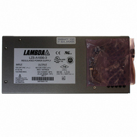
LZS-A1000-3 POWER SUPPLY Installation, Operation, and Maintenance Manual IM-L L ZSA1000-3 3 December 2009 Revision H ...
Page 2
...
Page 3
Table of Contents 1) Safety and Recommended Practices 1.1 General safety instructions 1.2 Safety Agency Approvals 2) RATINGS AND SPECIFICATIONS 3) FEATURES 4) GUIDE TO APPLICATION 4.1 Safety Notice 4.2 Input Voltage 4.3 Output Voltage 4.4 Overvoltage Protection Circuit Adjustment ...
Page 4
LZS-A A 1000-3 3 Power Supply 1 Safety and Recommended Practices 1.1 General Safety Instructions This power supply is a switch mode power supply for use in applications meeting a Pollution Degree 2 environment. A suitable mechanical and fire enclosure ...
Page 5
Emissions AC Line Conducted Emissions EN55022/EN55011 Radiated RF Emissions EN55022/EN55011 Powerline Harmonics EN61000-3-2 Powerline Fluctuation/Flicker EN61000-3-3 Immunity Electrostatic Discharge IEC61000-4-2 RF Radiated Fields IEC61000-4-3 Electrical Fast Transients IEC61000-4-4 Lightning Surge IEC61000-4-5 Conducted RF Common Mode IEC61000-4-6 Power Frequency Magnetic Field ...
Page 6
LZS-A A 1000-3 3 Power Supply This manual is a description of specifications, features and applications of LZS-A1000 power supplies. RATINGS AND SPECIFICATIONS * Maximum Ratings Output Voltage Range Output Current (Power) @ 60°C** DC Output @ 24V Output Current ...
Page 7
Operating Modes Series Operation Yes (see Fig. 7) Parallel Operation Two or more identical units (see Fig. 6). (Use of D. con. terminal 5 will (with current sharing) provide current sharing to within 10% nominal of rated 60°C current.) * ...
Page 8
LZS-A A 1000-3 3 Power Supply Protection Features Output Voltage Range Nominal Factory Set Point Overvoltage Protection (adjustable) Overcurrent Protection Thermal Protection Fusing Isolation Voltages Regulatory Agency Compliance Leakage current (AC line to chassis ground) * See “Overtemperature and Overvoltage ...
Page 9
... Overtemp shutdown resets itself once the unit has cooled off by approximately 10 4.6 AUXILIARY CONTROL AND ALARM SIGNALS LZSa power supplies provide auxiliary control and alarm signals per page 5. These signals are accessible via the15-pin, sub miniature "D" connector, located below the output terminals of the unit. 3055 Del Sol Blvd • ...
Page 10
LZS-A A 1000-3 3 Power Supply 5. Figures Figure 1 - PIN Assignments for TB201 and chassis mounted “D” connector Page. 8 Revision H : December 2009 ...
Page 11
LS = Local Sense S = Remote Sense Figure 2 - Typical Local Sense Connection LS = Local Sense S = Remote Sense Figure 3 - Typical Remote Sense Connection 3055 Del Sol Blvd • San Diego, CA 92154 • ...
Page 12
LZS-A A 1000-3 3 Power Supply LS = Local Sense S = Remote Sense Figure 4 - Remote Voltage Control with an External Programming Resistor or Voltage Source (Local Sensing Local Sense S = Remote Sense Figure 5 ...
Page 13
Figure 6 - Parallel Operation 3055 Del Sol Blvd • San Diego, CA 92154 • 1-800-LAMBDA-4 LZS-A A 1000-3 3 Power Supply Page. 11 Revision H : December 2009 ...
Page 14
LZS-A A 1000-3 3 Power Supply Figure 7 - Series Operation Page. 12 Revision H : December 2009 ...
Page 15
Figure 8 - Outline Drawing 3055 Del Sol Blvd • San Diego, CA 92154 • 1-800-LAMBDA-4 LZS-A A 1000-3 3 Power Supply Page. 13 Revision H : December 2009 ...
Page 16
LZS-A A 1000-3 3 Power Supply Figure 9 - Remote Output On/Off Control Figure 10 - Input Good, Inverter Good & Output Good Signals Page. 14 Revision H : December 2009 ...