LZSA-1000-3 TDK Corporation, LZSA-1000-3 Datasheet - Page 7
LZSA-1000-3
Manufacturer Part Number
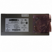
LZSA-1000-3
Description
PWR SUP 24V 1008W 42A
Manufacturer
TDK Corporation
Series
LZSAr
Type
Industrialr
Specifications of LZSA-1000-3
Power Supply Type
Switching (Closed Frame)
Voltage - Output
24V
Number Of Outputs
1
Power (watts)
1000W
Applications
Commercial
Voltage - Input
85 ~ 265VAC
Mounting Type
Chassis Mount
1st Output
24 VDC @ 42 A
Size / Dimension
10.5" L x 5.62" W x 4.75" H (266.7mm x 142.7mm x 120.7mm)
Power (watts) - Rated
1008W
Operating Temperature
-40°C ~ 71°C
Efficiency
84%
Approvals
CE, EN, UL
Line Regulation
0.1%
Load Regulation
0.1%
Power Supply Output Type
Fixed
No. Of Outputs
1
Output Voltage
24V
Output Current
42A
Power Rating
1008W
Input Voltage
85V AC To 265V AC / 100V DC To 400V DC
Brand/series
LZSA Series
Configuration
Enclosed
Operation
Linear
Output
24 VDC @ 42 A
Power, Output
1008 W
Primary Type
AC-DC
Special Features
High Reliability, Parallelable, Remote Adjust, Remote On/Off, Remote Sense
Voltage, Input
85 to 265/100 to 400 VAC/VDC
Voltage, Output
24 VDC
Input Frequency
47 to 440Hz
Screening Level
Commercial
Operating Temperature Min Deg. C
-40C
Operating Temperature Max Deg. C
71C
Mounting Style
Desktop
Lead Free Status / RoHS Status
Lead free / RoHS Compliant
3rd Output
-
2nd Output
-
4th Output
-
Lead Free Status / Rohs Status
RoHS Compliant part
Other names
285-1455
LZSA10003
LZSA10003
Available stocks
Company
Part Number
Manufacturer
Quantity
Price
Company:

Part Number:
LZSA-1000-3
Manufacturer:
TDK
Quantity:
100


FEATURES
3055 Del Sol Blvd • San Diego, CA 92154 • 1-800-LAMBDA-4
* Not backward compatible with the LZS-1000-3 power supply.
Operating Modes
Remote Control Features
Auxiliary Monitoring and Alarm Signals
DC Output Controls and Indicators
Series Operation
Parallel Operation
(with current sharing)
Output Voltage Adjust
Overvoltage Protection Adjust
Output Good Indicator
Fault Indicator
Remote Voltage Sensing
Remote Voltage Programming
external resistor.
Remote Voltage Programming
external voltage source.
Remote On/Off Control
Signals Isolation
Signal Logic
Signal Current Draw
Output Response Time
Signal Enable
Optically coupled, conductance outputs. (Conduct up to 1mA at a voltage of <0.4 V, when active.)
Input Power Good Signal
Output Good Alarm Signal
Inverter Good Signal
Signal Isolation
Synchronization (Sync)
Yes (see Fig. 7)
Two or more identical units (see Fig. 6). (Use of D. con. terminal 5 will
provide current sharing to within 10% nominal of rated 60°C current.)
Screwdriver adjustment over entire range. Output voltage range is from
18-29.4V. (Multi-turn potentiometer accessible from terminal end of chassis.)
Screwdriver adjustment over entire range. Overvoltage trip range is from
20-34V. Factory setpoint is 31.0V. (Multi-turn potentiometer accessible
from terminal end of chassis.)
Green colored LED illuminates when output is within specified operating range
Red colored LED illuminates if overvoltage, overtemperature, or overcurrent
shutdown occurs. The LED is also illuminated if the output is less than approximately
95% of its adjusted output or if the output is inhibited (stand-by mode).
Provides precise regulation directly at load (see Fig. 3). Maximum total
DC voltage drop between output terminals and load must be limited to
<1.0 V . In addition, the voltage at the output terminals must be limited to
29.4V.
1000 ohms per volt for resistor connected between pins 1 and 2
on TB201 (see Figs. 4 and 5).
Volt per volt for voltage source connected between pins 1 and 2
on TB201 (see Figs. 4 and 5).
Enable/Disable output via TTL compatible signal connected between
pins 6 and 7 of “D” connector (see Fig. 9).
Pins 6 and 7 are fully isolated from all other power supply terminals.
Logic zero (below 0.7 V), short circuit or open circuit disables power
supply output. Logic one (above 2.5 V) enables power supply output.
Current draw from Logic 1 input is less than 4mA.
Output will be within specified limits within 100 ms. of application of
logic “1” signal.
Remote on/off function must be enabled by moving “OUTPUT ENABLE”
switch at terminal end of chassis from “LOCAL” to “REMOTE” position (see Fig. 9).
Conductance signal which indicates adequate input capacitor voltage to
provide 10 ms holdup time when operating -3 model at full output power.
Signal will be asserted when the unit is remotely disabled (AC still present)
or when unit shuts down due to overtemperature (see Fig.10).
Conductance signal which indicates that delivered output voltage, as measured at
the +V and -V terminals, is above its minimum specified value (see Fig. 10).
Conductance signal which indicates that the power supply’s inverter is
functional. At very light loads, this signal may be indeterminate (see Fig. 10).
Input power good, output UV/OV alarms, inverter good and remote on/off
signals are isolated from power supply output and each other for voltages up
to 500 volts, minimum. 3000 VAC isolation from AC input to all auxiliary signals.
Auxiliary signal at approximately 200khz (switching frequency of unit) used for
synchronizing with other equipment.
LZS-A A 1000-3 3 Power Supply
Revision H : December 2009
Table 5
Table 7
Table 8
Table 6
Page. 5
Related parts for LZSA-1000-3
Image
Part Number
Description
Manufacturer
Datasheet
Request
R

Part Number:
Description:
PWR SUP 24V 504W 21A
Manufacturer:
TDK Corporation
Datasheet:
Part Number:
Description:
POWER SUPPLY, SWITCH MODE, 12V
Manufacturer:
TDK Corporation
Datasheet:
Part Number:
Description:
POWER SUPPLY, SWITCH MODE, 24V
Manufacturer:
TDK Corporation
Datasheet:
Part Number:
Description:
Manufacturer:
TDK Corporation
Datasheet:
Part Number:
Description:
Power Supply, Single Output, 1512 Watts, 24 V, 63A Max, Volt Adjust: 18 - 29.4
Manufacturer:
TDK Corporation
Datasheet:
Part Number:
Description:
Power Supply, Single Output, 1512 Watts, 24 V, 63A Max, Volt Adjust:18 - 29.4
Manufacturer:
TDK Corporation
Datasheet:
Part Number:
Description:
Power Supply, Single Output, 1512 Watts, 48V, 31.5A Max, 36-56V Adj.
Manufacturer:
TDK Corporation
Datasheet:
Part Number:
Description:
TDK DC to DC Converters, DC to AC Inverters
Manufacturer:
TDK Corporation
Datasheet:
Part Number:
Description:
TDK DC to DC Converters, DC to AC Inverters
Manufacturer:
TDK Corporation
Datasheet: