LTM4611EV#PBF Linear Technology, LTM4611EV#PBF Datasheet - Page 5
LTM4611EV#PBF
Manufacturer Part Number
LTM4611EV#PBF
Description
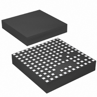
IC UMODULE DC/DC LV 15A 133-LGA
Manufacturer
Linear Technology
Series
µModuler
Type
Point of Load (POL) Non-Isolatedr
Datasheet
1.LTM4611EVPBF.pdf
(28 pages)
Specifications of LTM4611EV#PBF
Output
0.8 ~ 5 V
Number Of Outputs
1
Power (watts)
75W
Mounting Type
Surface Mount
Voltage - Input
1.5 ~ 5.5 V
Package / Case
133-LGA
1st Output
0.8 ~ 5 VDC @ 15A
Size / Dimension
0.59" L x 0.59" W x 0.17" H (15mm x 15mm x 4.32mm)
Power (watts) - Rated
75W
Operating Temperature
-40°C ~ 125°C
Efficiency
94%
Lead Free Status / RoHS Status
Lead free / RoHS Compliant
3rd Output
-
2nd Output
-
Available stocks
Company
Part Number
Manufacturer
Quantity
Price


SYMBOL
PLLFLTR/f
Frequency Nominal Nominal Frequency
Frequency Low
Frequency High
I
R
V
V
Mode_PLLIN
Clock
Note 1: Stresses beyond those listed under Absolute Maximum Ratings
may cause permanent damage to the device. Exposure to any Absolute
Maximum Rating condition for extended periods may affect device
reliability and lifetime.
Note 2: The LTM4611 is tested under pulsed load conditions such that
T
over the 0°C to 125°C operating junction temperature (T
Specifications over the full –40°C to 125°C operating junction temperature
range are assured by design, characterization and correlation with
statistical process controls. The LTM4611I is guaranteed to meet
specifications over the full –40°C to 125°C operating junction temperature
range. Note that the maximum ambient temperature consistent with
these specifications is determined by specific operating conditions in
conjunction with board layout, the rated package thermal resistance and
other environmental factors.
elecTrical characTerisTics
junction temperature range, otherwise specifications are at T
PLLFLTR
J
MODE(PLLIN)
IH
IL
≈ T
A
. The LTM4611E is guaranteed to meet performance specifications
SET(FLOAT)
PARAMETER
PLLFLTR/f
Voltage
Lowest Frequency
Highest Frequency
PLLFLTR
Mode_PLLIN Input Resistance
Clock Input Level High
Clock Input Level Low
Clock Input Duty Cycle Range
Sourcing Capability
Sinking Capability
SET
Open-Circuit
J
) range.
CONDITIONS
PLLFLTR/f
PLLFLTR/f
PLLFLTR/f
PLLFLTR/f
Mode_PLLIN Frequency > f
Mode_PLLIN Frequency < f
The
SET
SET
SET
SET
A
l
= 25°C, V
Pin Voltage When Floating
Floating
= 0.85V
= 2.0V
denotes the specifications which apply over the full internal operating
Note 3: Consistent with Pb-free 260°C peak IR reflow soldering profiles.
See Application Note 100.
Note 4: See output current derating curves for different V
Note 5: The minimum on-time condition is specified for a peak-to-peak
inductor ripple current of ~40% of I
section)
IN
OSC
OSC
= 3.3V, per the typical application in Figure 21.
MAX
MIN
2.0
40
Load. (See the Typical Applications
TYP
1.23
500
330
780
–13
250
13
50
LTM4611
IN
MAX
0.6
60
, V
OUT
and T
UNITS
4611f
kHz
kHz
kHz
A
kΩ
µA
µA
.
%
V
V
V
Related parts for LTM4611EV#PBF
Image
Part Number
Description
Manufacturer
Datasheet
Request
R

Part Number:
Description:
Ltm4611 Ultralow Vin, 15a Dc/dc ?module Regulator Features
Manufacturer:
Linear Technology Corporation
Datasheet:

Part Number:
Description:
CD ROM LINEARVIEW DATASHEETS
Manufacturer:
Linear Technology
Part Number:
Description:
Standalone Linear Li-Ion Battery Charger with Thermal Regulation in ThinSOT
Manufacturer:
Linear Technology Corporation
Datasheet:
Part Number:
Description:
Low noise, high frequency, 8th order linear phase lowpass filter
Manufacturer:
Linear Technology Corporation
Datasheet:
Part Number:
Description:
Manufacturer:
Linear Technology Corporation
Datasheet:
Part Number:
Description:
Manufacturer:
Linear Technology Corporation
Datasheet:
Part Number:
Description:
Manufacturer:
Linear Technology Corporation
Datasheet:
Part Number:
Description:
Manufacturer:
Linear Technology Corporation
Datasheet:
Part Number:
Description:
Manufacturer:
Linear Technology Corporation
Datasheet:
Part Number:
Description:
Manufacturer:
Linear Technology Corporation
Datasheet:
Part Number:
Description:
Manufacturer:
Linear Technology Corporation
Datasheet:
Part Number:
Description:
Dual and Quad, JFET Input Precision High Speed Op Amps
Manufacturer:
Linear Technology Corporation
Datasheet:
Part Number:
Description:
Manufacturer:
Linear Technology Corporation
Datasheet:
Part Number:
Description:
1, 2, 6 and 8 Channel, 10-Bit Serial I/O Data Acquisition Systems
Manufacturer:
Linear Technology Corporation
Datasheet:
Part Number:
Description:
Manufacturer:
Linear Technology Corporation
Datasheet: