LTM4611EV#PBF Linear Technology, LTM4611EV#PBF Datasheet - Page 16
LTM4611EV#PBF
Manufacturer Part Number
LTM4611EV#PBF
Description
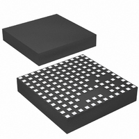
IC UMODULE DC/DC LV 15A 133-LGA
Manufacturer
Linear Technology
Series
µModuler
Type
Point of Load (POL) Non-Isolatedr
Datasheet
1.LTM4611EVPBF.pdf
(28 pages)
Specifications of LTM4611EV#PBF
Output
0.8 ~ 5 V
Number Of Outputs
1
Power (watts)
75W
Mounting Type
Surface Mount
Voltage - Input
1.5 ~ 5.5 V
Package / Case
133-LGA
1st Output
0.8 ~ 5 VDC @ 15A
Size / Dimension
0.59" L x 0.59" W x 0.17" H (15mm x 15mm x 4.32mm)
Power (watts) - Rated
75W
Operating Temperature
-40°C ~ 125°C
Efficiency
94%
Lead Free Status / RoHS Status
Lead free / RoHS Compliant
3rd Output
-
2nd Output
-
Available stocks
Company
Part Number
Manufacturer
Quantity
Price


LTM4611
applicaTions inForMaTion
Decreasing the PLLFLTR/f
accomplished, for example, by driving the PLLFLTR/f
pin with an external, lower impedance resistor divider
network from INTV
simplest of implementations, by shorting PLLFLTR/f
to INTV
to 780kHz, nominal), or by driving the PLLFLTR/f
from a low impedance voltage source.
When, in addition to needing faster turn-on time, one is also
synchronizing to an external clock signal, one need bear in
mind: the PLL’s sink and source current is recommended
for not more than ±8µA loading, and the PLL will need
to successfully drive any external PLLFLTR/f
impedance to achieve phase lock; and lastly, some phase
shift in clock synchronization will occur as external loading
on PLLFLTR/f
To be clear, using a C
the need for any of the above special considerations or
provisions.
Ratiometric tracking can be achieved by a few simple
calculations and the slew rate value applied to the master’s
TRACK/SS pin. As mentioned above, the TRACK/SS pin has
a control range from 0V to 0.8V. The master’s TRACK/SS
pin slew rate is directly equal to the master’s output slew
rate in volts/time. The equation:
where MR is the master’s output slew rate and SR is the
slave’s output slew rate in volts/time. When coincident
tracking is desired, then MR and SR are equal, thus R
is equal to 60.4k. R
where V
tor, and V
top feedback resistor of the slave regulator in equal slew
rate or coincident tracking, then R
V
Figure 4.
FB
R
MR
SR
= V
TA
=
• 60.4k = R
CC
TRACK
FB
60.4k
(thereby programming the switching frequency
TRACK
V
is the feedback voltage reference of the regula-
FB
. Therefore R
SET
+
is 0.8V. Since R
becomes heavier.
R
TB
V
0.8V
CC
TA
FB2
SS
FB
and GND to PLLFLTR/f
is derived from equation:
value of 10nF (or higher) eliminates
–
V
SET
TB
TRACK
R
TB
= 60.4k, and R
RC time constant can be
TB
TA
is equal to the 60.4k
is equal to R
SET
TA
SET
= 121k in
—in the
network
FB2
SET
with
SET
SET
pin
TB
In ratiometric tracking, a different slew rate maybe desired
for the slave regulator. R
slower than MR. Make sure that the slave supply slew rate
is chosen to be fast enough so that the slave output voltage
will reach its final value before the master output.
For example, MR = 1.5V/ms, and SR = 1.2V/ms. Then R
= 75k. Solve for R
Beware that without any kind of soft-start ramp up, it is
important to provide thorough input filter capacitance to
handle input surge currents at start-up, so as to avoid
excessive input line sag and power supply motor boating.
Leaving provision for at least a soft-start capacitor in one’s
application is strongly recommended.
Overcurrent and Overvoltage Protection
The LTM4611 has overcurrent protection (OCP) in a
short circuit. The internal current comparator threshold
folds back during a short to reduce the output current.
An overvoltage condition (OVP) above 7.5% of the regu-
lated output voltage will force the top MOSFET off and
the bottom MOSFET on until the condition is cleared. An
input electronic circuit breaker or fuse can be sized to be
tripped or cleared when the bottom MOSFET is turned on
to protect against the overvoltage. Foldback current limiting
is disabled during soft-start or tracking start-up.
Run Enable
The RUN pin is used to enable the power module or
sequence the power module. The threshold is 1.22V. The
RUN pin must be used as an undervoltage lockout (UVLO)
function by connecting a resistor divider from the input
supply to the RUN pin:
To achieve the lowest possible UVLO, 1.22V, leave R2
unpopulated. R1 can be 10k, or if R2 is unpopulated, R1
may be replaced with a hardwired connection from V
to RUN.
R2 =
1.22V
V
UVLO
R1
– 1
TA
to equal to 87k.
TB
can be solved for when SR is
4611f
TB
IN
Related parts for LTM4611EV#PBF
Image
Part Number
Description
Manufacturer
Datasheet
Request
R

Part Number:
Description:
Ltm4611 Ultralow Vin, 15a Dc/dc ?module Regulator Features
Manufacturer:
Linear Technology Corporation
Datasheet:

Part Number:
Description:
CD ROM LINEARVIEW DATASHEETS
Manufacturer:
Linear Technology
Part Number:
Description:
Standalone Linear Li-Ion Battery Charger with Thermal Regulation in ThinSOT
Manufacturer:
Linear Technology Corporation
Datasheet:
Part Number:
Description:
Low noise, high frequency, 8th order linear phase lowpass filter
Manufacturer:
Linear Technology Corporation
Datasheet:
Part Number:
Description:
Manufacturer:
Linear Technology Corporation
Datasheet:
Part Number:
Description:
Manufacturer:
Linear Technology Corporation
Datasheet:
Part Number:
Description:
Manufacturer:
Linear Technology Corporation
Datasheet:
Part Number:
Description:
Manufacturer:
Linear Technology Corporation
Datasheet:
Part Number:
Description:
Manufacturer:
Linear Technology Corporation
Datasheet:
Part Number:
Description:
Manufacturer:
Linear Technology Corporation
Datasheet:
Part Number:
Description:
Manufacturer:
Linear Technology Corporation
Datasheet:
Part Number:
Description:
Dual and Quad, JFET Input Precision High Speed Op Amps
Manufacturer:
Linear Technology Corporation
Datasheet:
Part Number:
Description:
Manufacturer:
Linear Technology Corporation
Datasheet:
Part Number:
Description:
1, 2, 6 and 8 Channel, 10-Bit Serial I/O Data Acquisition Systems
Manufacturer:
Linear Technology Corporation
Datasheet:
Part Number:
Description:
Manufacturer:
Linear Technology Corporation
Datasheet: