MT16LSDF6464HG-133D2 Micron Technology Inc, MT16LSDF6464HG-133D2 Datasheet - Page 2
MT16LSDF6464HG-133D2
Manufacturer Part Number
MT16LSDF6464HG-133D2
Description
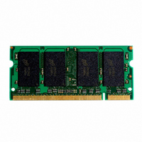
MODULE SDRAM 512MB 144SODIMM
Manufacturer
Micron Technology Inc
Specifications of MT16LSDF6464HG-133D2
Memory Type
SDRAM
Memory Size
512MB
Speed
133MHz
Package / Case
144-SODIMM
Main Category
DRAM Module
Sub-category
SDRAM
Module Type
144SODIMM
Device Core Size
64b
Organization
64Mx64
Total Density
512MByte
Chip Density
256Mb
Access Time (max)
6/5.4ns
Maximum Clock Rate
133MHz
Operating Supply Voltage (typ)
3.3V
Operating Current
1.096A
Number Of Elements
16
Operating Supply Voltage (max)
3.6V
Operating Supply Voltage (min)
3V
Operating Temp Range
0C to 70C
Operating Temperature Classification
Commercial
Pin Count
144
Mounting
Socket
Lead Free Status / RoHS Status
Contains lead / RoHS non-compliant
Available stocks
Company
Part Number
Manufacturer
Quantity
Price
Company:

Part Number:
MT16LSDF6464HG-133D2
Manufacturer:
MICRON
Quantity:
1


PART NUMBERS
NOTE: All part numbers end with a five-place code, of
ADDRESS TABLE
GENERAL DESCRIPTION
MT16LSDF6464HG are high-speed CMOS, dynamic
random-access, 256MB and 512MB memory modules,
organized in a x64 configuration. These modules use
SDRAMs that are internally configured as quad-bank
DRAMs with a synchronous interface (all signals are
registered on the positive edge of the clock signal CK0).
Read and write accesses to the SDRAM modules is burst
oriented; accesses start at a selected location and con-
tinue for a programmed number of locations in a pro-
grammed sequence. Accesses begin with the registra-
tion of an ACTIVE command, which is then followed by
a READ or WRITE command. The address bits regis-
tered coincident with the ACTIVE command are used
to select the device bank and row to be accessed (BA0,
BA1 select the device bank, A0-A11 select the device
row for the 256MB module; A0-A12 for the 512MB
32/64 Meg x 64 SDRAM SODIMM
SD16C32_64x64HG_A.pm6; Rev. A, Pub 7/01
Refresh Count
Device Banks
Row Addressing
Column Addressing
Module Banks
Base Device Configuration
MT16LSDF3264HG-13E__
MT16LSDF3264HG-133__
MT16LSDF3264HG-10E__
MT16LSDF6464HG-13E__
MT16LSDF6464HG-133__
MT16LSDF6464HG-10E__
The
PART NUMBER
which last two are not shown designating compo-
nent and PCB revisions. Consult factory for current
revision codes. Example: MT16LSDF3264HG-133B1.
Micron
®
CONFIGURATION
256MB Module
4 (BA0, BA1)
4K (A0–A11)
1K (A0–A9)
2 (S0#, S1#)
16 Meg x 8
MT16LSDF3264HG
32 Meg x 64
32 Meg x 64
32 Meg x 64
64 Meg x 64
64 Meg x 64
64 Meg x 64
4K
512MB Module
4 (BA0, BA1)
8K (A0–A12)
1K (A0–A9)
2 (S0#, S1#)
133 MHz, CL = 2
133 MHz, CL = 3
100 MHz, CL = 2
133 MHz, CL = 2
133 MHz, CL = 3
100 MHz, CL = 2
32 Meg x 8
VERSION
8K
and
2
module). The address bits registered coincident with
the READ or WRITE command are used to select the
starting column location for the burst access.
WRITE burst lengths of 1, 2, 4, or 8 locations, or the full
page, with a burst terminate option. An auto precharge
function may be enabled to provide a self-timed de-
vice row precharge that is initiated at the end of the
burst sequence.
pipelined architecture to achieve high-speed opera-
tion. This architecture is compatible with the 2n rule of
prefetch architectures, but it also allows the device
column address to be changed on every clock cycle to
achieve
Precharging one device bank while accessing the alter-
nate device bank will hide the PRECHARGE cycles and
provide seamless, high-speed, random-access opera-
tion.
power memory systems. An auto refresh mode is pro-
vided, along with a power-saving, power-down mode.
All inputs, outputs and clocks are LVTTL-compatible.
DRAM operating performance, including the ability to
synchronously burst data at a high data rate with auto-
matic column-address generation, the ability to inter-
leave between device banks in order to hide precharge
time, and the capability to randomly change device
column addresses on each clock cycle during a burst
access. For more information regarding SDRAM opera-
tion, refer to the 128Mb and 256Mb data sheets.
SERIAL PRESENCE-DETECT OPERATION
(SPD). The SPD function is implemented using a 2,048-
bit EEPROM. This nonvolatile storage device contains
256 bytes. The first 128 bytes can be programmed by
Micron to identify the module type and various SDRAM
organizations and timing parameters. The remaining
128 bytes of storage are available for use by the cus-
tomer. System READ/WRITE operations between the
master (system logic) and the slave EEPROM device
(DIMM) occur via a standard IIC bus using the DIMM’s
SCL (clock) and SDA (data) signals.
Micron Technology, Inc., reserves the right to change products or specifications without notice.
These modules provide for programmable READ or
These modules are designed to operate in 3.3V, low-
SDRAM modules offer substantial advances in
These modules incorporate serial presence-detect
a
high-speed,
These modules use an internal
SDRAM SODIMM
256/512MB (x64)
fully
random
PRELIMINARY
©2001, Micron Technology, Inc.
access.
Related parts for MT16LSDF6464HG-133D2
Image
Part Number
Description
Manufacturer
Datasheet
Request
R

Part Number:
Description:
IC SDRAM 64MBIT 133MHZ 54TSOP
Manufacturer:
Micron Technology Inc
Datasheet:

Part Number:
Description:
IC SDRAM 64MBIT 5.5NS 86TSOP
Manufacturer:
Micron Technology Inc
Datasheet:
Part Number:
Description:
IC SDRAM 64MBIT 200MHZ 86TSOP
Manufacturer:
Micron Technology Inc
Datasheet:
Part Number:
Description:
IC SDRAM 64MBIT 133MHZ 54TSOP
Manufacturer:
Micron Technology Inc
Datasheet:
Part Number:
Description:
IC SDRAM 128MBIT 133MHZ 54TSOP
Manufacturer:
Micron Technology Inc
Datasheet:

Part Number:
Description:
IC SDRAM 256MBIT 133MHZ 90VFBGA
Manufacturer:
Micron Technology Inc
Datasheet:
Part Number:
Description:
IC SDRAM 128MBIT 133MHZ 54TSOP
Manufacturer:
Micron Technology Inc
Datasheet:
Part Number:
Description:
IC SDRAM 256MBIT 133MHZ 54TSOP
Manufacturer:
Micron Technology Inc
Datasheet:

Part Number:
Description:
IC DDR SDRAM 512MBIT 6NS 66TSOP
Manufacturer:
Micron Technology Inc
Datasheet:
Part Number:
Description:
IC SDRAM 128MBIT 167MHZ 86TSOP
Manufacturer:
Micron Technology Inc
Datasheet:
Part Number:
Description:
IC SDRAM 128MBIT 143MHZ 86TSOP
Manufacturer:
Micron Technology Inc
Datasheet:

Part Number:
Description:
SDRAM 256M-BIT 1.8V 54-PIN VFBGA
Manufacturer:
Micron Technology Inc
Datasheet:
Part Number:
Description:
IC SDRAM 128MBIT 143MHZ 86TSOP
Manufacturer:
Micron Technology Inc
Datasheet:

Part Number:
Description:
IC SDRAM 128MBIT 125MHZ 54VFBGA
Manufacturer:
Micron Technology Inc
Datasheet:
Part Number:
Description:
IC SDRAM 128MBIT 125MHZ 54VFBGA
Manufacturer:
Micron Technology Inc
Datasheet: