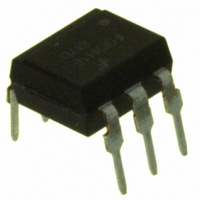
FOD4116 Fairchild Semiconductor, FOD4116 Datasheet

FOD4116
Specifications of FOD4116
Related parts for FOD4116
FOD4116 Summary of contents
Page 1
... SCRs which form the triac function capable of driving discrete triacs. The FOD4116 and FOD4118 utilize a high efficiency infrared emitting diode which offers an improved trigger sensitivity. These devices are housed in a standard 6-pin dual in-line (DIP) package ...
Page 2
... For this test, Pins 1, 2 and 3 are common, ISO and Pins 4, 5 and 6 are common. 5,000 VRMS for 1 minute duration is equivalent to 6,000 VRMS for 1 second duration. ©2004 Fairchild Semiconductor Corporation FOD410, FOD4108, FOD4116, FOD4118 Rev. 1.5 25°C unless otherwise noted) A (1) ...
Page 3
... Critical Rate of Rise of crq Voltage at Current Commutation di/dt Critical Rate of Rise of cr On-State Current dV(IO)/dt Critical Rate of Rise of Coupled Input/Output Voltage *Typical values 25°C A ©2004 Fairchild Semiconductor Corporation FOD410, FOD4108, FOD4116, FOD4118 Rev. 1.5 25°C Unless otherwise specified) A Test Conditions I = 20mA 800V ...
Page 4
... A Notes: 2. Test voltage must be applied within dv/dt rating. 3. All devices are guaranteed to trigger lies between max I (2mA for FOD410 and FOD4108 and 1.3mA for FOD4116 and FOD4118 and the absolute F FT max I (60mA This is static dv/dt. See Figure 11 for test circuit. Commutating dv/ function of the load-driving thyristor(s) only. ...
Page 5
... Figure 6. Pulse Trigger Current 1.7 1.6 1.5 1.4 1.3 1.2 1.1 1.0 0.9 0 200 400 P – PULSE WIDTH (µs) W ©2004 Fairchild Semiconductor Corporation FOD410, FOD4108, FOD4116, FOD4118 Rev. 1.5.0 ) vs. Forward Current ( 1.6 V Normalized to T 1.4 1.2 1.0 0.8 0.6 -60 10 100 100 t ...
Page 6
... T – AMBIENT TEMPERATURE (°C) A Figure 10. Normalized Inhibit Voltage (V vs. Ambient Temperature (T 1.2 1.1 1.0 0.9 0.8 -60 -40 - – AMBIENT TEMPERATURE (°C) A ©2004 Fairchild Semiconductor Corporation FOD410, FOD4108, FOD4116, FOD4118 Rev. 1.5.0 (Continued Normalized 25° 800V Normalized 0.1 - 100 ) Figure 11. Normalized Leakage in Inhibit State (I ...
Page 7
... X100 PROBE MOUNT DUT ON TEMPERATURE CONTROLLED Cu PLATE 1N914 20V 100 s 50 PULSE GENERATOR Figure 11. Circuit for Static ©2004 Fairchild Semiconductor Corporation FOD410, FOD4108, FOD4116, FOD4118 Rev. 1.5 300 FOD410 2 FOD4108 MOC3011 FOD4116 4 FOD4118 7400 NOTE: Circuit supplies 25mA drive to gate of triac ...
Page 8
... Suggested method of firing two, back-to-back SCR’s with a Fairchild triac driver. Diodes can be 1N4001; resistors, R1 and R2, are optional 330 . Note: This optoisolator should not be used to drive a load directly intended discrete triac driver device only. ©2004 Fairchild Semiconductor Corporation FOD410, FOD4108, FOD4116, FOD4118 Rev. 1.5 ...
Page 9
... Pin 1 1.15~1.35 2.30~3.30 0.40~0.60 2.29~2.79 Note: All dimensions are in millimeters. ©2004 Fairchild Semiconductor Corporation FOD410, FOD4108, FOD4116, FOD4118 Rev. 1.5.0 Surface Mount 6.80~7.80 7.62 (Typ.) 2.29~2.70 0.26 (Typ.) Recommended Pad Layout for Surface Mount Leadforms 15 (Max.) 10.16 (Typ.) 0.26 (Typ ...
Page 10
... One digit year code, e.g., ‘7’ 5 Two digit work week ranging from ‘01’ to ‘53’ 6 Assembly package code ©2004 Fairchild Semiconductor Corporation FOD410, FOD4108, FOD4116, FOD4118 Rev. 1.5.0 Description Standard Through Hole Device Surface Mount Lead Bend Surface Mount; Tape and reel 0.4" Lead Spacing IEC60747-5-2 certifi ...
Page 11
... MAX Note: All dimensions are in inches (millimeters). Reflow Profile 300 250 200 150 100 50 ©2004 Fairchild Semiconductor Corporation FOD410, FOD4108, FOD4116, FOD4118 Rev. 1.5.0 12.0 0.1 2.0 0.1 4.0 0.1 0.05 User Direction of Feed 260C peak Time above 183C, <160 sec Ramp up = 2– ...
Page 12
... Product Status Advance Information Formative / In Design First Production Preliminary No Identification Needed Full Production Obsolete Not In Production ©2004 Fairchild Semiconductor Corporation FOD410, FOD4108, FOD4116, FOD4118 Rev. 1.5.0 ® PowerTrench ® PowerXS™ SM Programmable Active Droop™ ® QFET QS™ Quiet Series™ ...


