LT3695EMSE#PBF Linear Technology, LT3695EMSE#PBF Datasheet - Page 9
LT3695EMSE#PBF
Manufacturer Part Number
LT3695EMSE#PBF
Description
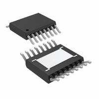
IC SWIT REG BUCK 1A ADJ 16MSOP
Manufacturer
Linear Technology
Type
Step-Down (Buck)r
Datasheet
1.LT3695EMSEPBF.pdf
(30 pages)
Specifications of LT3695EMSE#PBF
Internal Switch(s)
Yes
Synchronous Rectifier
No
Number Of Outputs
1
Voltage - Output
0.8 ~ 20 V
Current - Output
1A
Frequency - Switching
250kHz ~ 2.2MHz
Voltage - Input
3.6 ~ 36 V
Operating Temperature
-40°C ~ 125°C
Mounting Type
Surface Mount
Package / Case
16-MSOP Exposed Pad
Lead Free Status / RoHS Status
Lead free / RoHS Compliant
Power - Output
-
Available stocks
Company
Part Number
Manufacturer
Quantity
Price


PIN FUNCTIONS
PGND (Pin 1, Exposed Pad Pin 17/Pin 1, Exposed Pad
Pin 17): This is the power ground used by the catch diode
(D1 in the Block Diagram) when its anode is connected to
the DA pin. The exposed pad may be soldered to the PCB
in order to lower the thermal resistance.
DA (Pin 2/Pin 2): Connect the anode of the catch diode
(D1) to this pin. Internal circuitry senses the current
through the catch diode providing frequency foldback in
extreme situations.
NC (Pins 3, 10, 12/Pins 3, 10, 15): No Connects. These
pins are not connected to internal circuitry and must be
left fl oating to ensure fault tolerance.
SW (Pin 4/Pin 4): The SW pin is the output of the internal
power switch. Connect this pin to the inductor, catch diode
and boost capacitor.
RUN/SS (Pin 5/Pin 5): The RUN/SS pin is used to put
the LT3695 regulators in shutdown mode. Tie to ground
to shut down the LT3695 regulators. Tie to 2.5V or more
for normal operation. RUN/SS also provides a soft-start
function; see the Applications Information section for
more information.
RT (Pin 6/Pin 6): Oscillator Resistor Input. Connect a
resistor from this pin to ground to set the switching
frequency.
SYNC (Pin 7/Pin 7): This is the external clock synchroni-
zation input. Ground this pin with a 100k resistor for low
ripple Burst Mode operation at low output loads. Tie to
0.8V or more for pulse-skipping mode operation. Tie to a
clock source for synchronization. Clock edges should have
rise and fall times faster than 1μs. Note that the maximum
load current depends on which mode is chosen. See the
Applications Information section for more information.
(LT3695/LT3695-3.3, LT3695-5)
V
internal regulator and to the internal power switch. This
pin must be locally bypassed.
V
error amplifi er. The voltage on this pin controls the peak
switch current. Tie an RC network from this pin to ground
to compensate the control loop.
FB (Pin 11) LT3695: The LT3695 regulates the FB pin to 0.8V.
Connect the feedback resistor divider tap to this pin.
PG (Pin 13/Pin 11): The PG pin is the open-collector output
of an internal comparator. PG remains low until the FB pin
(LT3695) or the OUT1,2 pins (LT3695-3.3, LT3695-5) are
within 10% of the fi nal regulation voltage. PG output is
valid when V
RUN/SS is high.
GND (Pin 14/Pin 12): The GND pin is the ground of all the
internal circuitry. Tie directly to the local GND plane.
OUT1, OUT2, (Pins 14, 13) LT3695-3.3, LT3695-5: These
pins connect to the anode of the boost Schottky diode and
also supply current to the internal regulator. They also
connect to the internal feedback resistors and must be
connected to the output.
BD (Pin 15) LT3695: This pin connects to the anode of
the boost Schottky diode and also supplies current to the
LT3695’s internal regulator.
BOOST (Pin 16/Pin 16): This pin is used to provide a
drive voltage, higher than the input voltage, to the internal
bipolar NPN power switch. Connect a capacitor (typically
0.22μF) between BOOST and SW.
IN
C
(Pin 9/Pin 9): The V
(Pin 8/Pin 8): The V
IN
is above the minimum input voltage and
C
pin is the output of the internal
IN
pin supplies current to the
LT3695 Series
3695fa
9
Related parts for LT3695EMSE#PBF
Image
Part Number
Description
Manufacturer
Datasheet
Request
R

Part Number:
Description:
1a Fault Tolerant Micropower Step-down Regulator
Manufacturer:
Linear Technology Corporation
Datasheet:

Part Number:
Description:
CD ROM LINEARVIEW DATASHEETS
Manufacturer:
Linear Technology
Part Number:
Description:
Standalone Linear Li-Ion Battery Charger with Thermal Regulation in ThinSOT
Manufacturer:
Linear Technology Corporation
Datasheet:
Part Number:
Description:
Low noise, high frequency, 8th order linear phase lowpass filter
Manufacturer:
Linear Technology Corporation
Datasheet:
Part Number:
Description:
Manufacturer:
Linear Technology Corporation
Datasheet:
Part Number:
Description:
Manufacturer:
Linear Technology Corporation
Datasheet:
Part Number:
Description:
Manufacturer:
Linear Technology Corporation
Datasheet:
Part Number:
Description:
Manufacturer:
Linear Technology Corporation
Datasheet:
Part Number:
Description:
Manufacturer:
Linear Technology Corporation
Datasheet:
Part Number:
Description:
Manufacturer:
Linear Technology Corporation
Datasheet:
Part Number:
Description:
Manufacturer:
Linear Technology Corporation
Datasheet:
Part Number:
Description:
Dual and Quad, JFET Input Precision High Speed Op Amps
Manufacturer:
Linear Technology Corporation
Datasheet:
Part Number:
Description:
Manufacturer:
Linear Technology Corporation
Datasheet:
Part Number:
Description:
1, 2, 6 and 8 Channel, 10-Bit Serial I/O Data Acquisition Systems
Manufacturer:
Linear Technology Corporation
Datasheet:
Part Number:
Description:
Manufacturer:
Linear Technology Corporation
Datasheet: