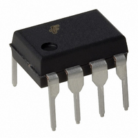
KA3844B Fairchild Semiconductor, KA3844B Datasheet

KA3844B
Specifications of KA3844B
Available stocks
Related parts for KA3844B
KA3844B Summary of contents
Page 1
... MOSFET. The KA3842B and KA3844B have UVLO thresholds of 16V (on) and 10V (off). The KA3843B and KA3845B are 8.5V (on) and 7.9V (off). The KA3842B and KA3843B can operate within 100% duty cycle ...
Page 2
... KA3842B/KA3843B/KA3844B/KA3845B Absolute Maximum Ratings Parameter Supply Voltage Output Current Analog Inputs (Pin 2.3) Error Amp Output Sink Current Power Dissipation (8DIP) A Power Dissipation (14SOP) A Storage Temperature Range Lead Temperature (Soldering, 10sec) Note: 1. Board Thickness 1.6mm, Board Dimension 76.2mm 114.3mm, (Reference EIA / JSED51-3, 51-7) 2 ...
Page 3
... I(MAX) pin1 PSRR 12V V 25V (Note1, BIAS I = 20mA SINK 200mA SINK I = 20mA SOURCE 200mA SOURCE 1nF (Note 1nF (Note KA3842B/KA3844B V TH(ST) KA3843B/KA3845B KA3842B/KA3844B V OPR(MIN) KA3843B/KA3845B KA3842B/KA3843B/KA3844B/KA3845B Min. Typ. Max. Unit 4.90 5.00 5. -100 -180 0. 1 -0.1 -2 2.42 2. -0.6 -1 GND 5 ...
Page 4
... High peak currents associated with capacitive loads necessitate careful grounding techniques Timing and bypass capacitors should be connected close to pin single point ground. The transistor and 5K potentiometer are used to sample the oscillator waveform and apply an adjustable ramp to pin 3. 4 (Continued +70 C unless otherwise specified) A Symbol Conditions D KA3842B/KA3843B (Max) D KA3844B/KA3845B (MAX (MIN =ON CC(OPR) ...
Page 5
... During Under-Voltage Lock-Out, the output driver is biased to a high impedance state. Pin 6 should be shunted to ground with a bleeder resistor to prevent activating the power switch with output leakage current. Peak current ( determined by the formula: S 1.0V I MAX = ----------- - small RC filter may be required to suppress switch transients. Figure 2. Under Voltage Lockout Figure 3. Error Amp Configuration Figure 4. Current Sense Circuit KA3842B/KA3843B/KA3844B/KA3845B 5 ...
Page 6
... KA3842B/KA3843B/KA3844B/KA3845B Figure 5. Oscillator Waveforms and Maximum Duty Cycle Oscillator timing capacitor charged charge time, the internal clock signal blanks the output to the low state. Selection of R oscillator frequency and maximum duty cycle. Charge and discharge times are determined by the formulas 0.55 R ...
Page 7
... A fraction of the oscillator ramp can be resistively summed with the current sense signal to provide slope compensation for converters requiring duty cycles over 50%. Note that capacitor, C spikes. TEMPERATURE ( C) Figure 10. Temperature Drift (Vref) TEMPERATURE ( C) Figure 12. Temperature Drift (Icc) Figure 9. Slope Compensation , forms a filter with R2 to suppress the leading edge switch T Figure 11. Temperature Drift (Ist) KA3842B/KA3843B/KA3844B/KA3845B TEMPERATURE ( C) 7 ...
Page 8
... KA3842B/KA3843B/KA3844B/KA3845B Mechanical Dimensions Package 6.40 0.20 0.252 0.008 # 7.62 0.300 8 Dimensions in millimeters 8-DIP 5.08 MAX 0.200 3.40 0.33 0.20 MIN 0.013 0.134 0.008 3.30 0.30 0.130 0.012 ...
Page 9
... Mechanical Dimensions Package #1 #7 6.00 0.236 3.95 0.156 5.72 0.225 0.60 0.20 0.024 0.008 (Continued) Dimensions in millimeters 14-SOP 1.55 0.10 0.061 0.004 #14 #8 0.30 1.80 MAX 0.071 0.012 0.20 0.008 KA3842B/KA3843B/KA3844B/KA3845B 0.05 MIN 0.002 9 ...
Page 10
... KA3844B KA3845B KA3842BD KA3843BD 14-SOP KA3844BD KA3845BD DISCLAIMER FAIRCHILD SEMICONDUCTOR RESERVES THE RIGHT TO MAKE CHANGES WITHOUT FURTHER NOTICE TO ANY PRODUCTS HEREIN TO IMPROVE RELIABILITY, FUNCTION OR DESIGN. FAIRCHILD DOES NOT ASSUME ANY LIABILITY ARISING OUT OF THE APPLICATION OR USE OF ANY PRODUCT OR CIRCUIT DESCRIBED HEREIN; NEITHER DOES IT CONVEY ANY LICENSE UNDER ITS PATENT RIGHTS, NOR THE RIGHTS OF OTHERS ...


