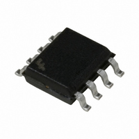
FAN7554DTF Fairchild Semiconductor, FAN7554DTF Datasheet - Page 9

FAN7554DTF
Manufacturer Part Number
FAN7554DTF
Description
IC CTRLR PWM CURRENT MODE 8SOIC
Manufacturer
Fairchild Semiconductor
Datasheet
1.FAN7554DTF.pdf
(22 pages)
Specifications of FAN7554DTF
Pwm Type
Current Mode
Number Of Outputs
1
Frequency - Max
500kHz
Duty Cycle
98%
Voltage - Supply
9 V ~ 30 V
Buck
No
Boost
No
Flyback
Yes
Inverting
No
Doubler
No
Divider
No
Cuk
No
Isolated
Yes
Operating Temperature
-25°C ~ 85°C
Package / Case
8-SOIC (3.9mm Width)
Frequency-max
500kHz
Output Current
1 A
Switching Frequency
500 KHz
Mounting Style
SMD/SMT
Maximum Operating Temperature
+ 85 C
Minimum Operating Temperature
- 25 C
Lead Free Status / RoHS Status
Lead free / RoHS Compliant
Other names
FAN7554DTFTR
FAN7554DTF_NL
FAN7554DTF_NLTR
FAN7554DTF_NLTR
FAN7554DTF_NL
FAN7554DTF_NLTR
FAN7554DTF_NLTR
Available stocks
Company
Part Number
Manufacturer
Quantity
Price
Part Number:
FAN7554DTF
Manufacturer:
FAIRCHILD/仙童
Quantity:
20 000
Oscillator
As shown in figure14, the oscillator frequency is programmed by values selected for timing components Rt and C
C
The oscillator generates the clock signal while the timing capacitor C
the clock time. Rt and C
can be calculated through the equations below.
t
Ct
Ct
Rt
Rt
is charged to almost 2.8V through resistor Rt from the 5V reference and discharged to 1.2V by an internal current source.
Ct
CT
CT
Vref
Vref
4
4
8
8
Cs
Cs
Figure 14. Oscillator Circuit
Discharge
Discharge
Discharge
t
2.8V
2.8V
/1.2V
/1.2V
selection determine the oscillator frequency and maximum duty cycle. Charge and discharge times
+
-
Charging time : tc = 0.55 R
Discharging time : td = R
where the oscillator frequency : fosc = (tc + td)
When R
Cfb
Cfb
Figure 13. Soft Start Circuit & Circuit Flow
S/S
S/S
2
2
FB
FB
t
Clock
1
1
Gate Drive
Gate Drive
> 5k , fosc = 1 / (0.55 R
FAN7554
FAN7554
1mA
1mA
5uA
5uA
Ds
Ds
5V
5V
Sawtooth waveform
Sawtooth waveform
Sawtooth waveform
Sawtooth waveform
100uA
100uA
Vcc
Vcc
t
C
t
Vlow(1.2V)
Vlow(1.2V)
Vlow(1.2V)
Vlow(1.2V)
Vhigh(2.8V)
Vhigh(2.8V)
Internal clock
Internal clock
Vhigh(2.8V)
Vhigh(2.8V)
Internal clock
Internal clock
t
C
ln[(0.0063 R
t
t
is discharged. The gate drive output becomes low during
5V
5V
t
2R
2R
C
t
R
R
R
R
) = 1.8 / (R
Figure 15. Sawtooth & Clock Waveform
t
tc
tc
- 2.8) / (0.0063 R
tc
tc
-1
(±10%)
td
td
t
td
td
C
t
)
FAN7554
FAN7554
t
- 3.8)]
Output drive
Output drive
t
. Capacitor
[ Rt > 5k ]
[ Rt > 5k ]
[ Rt < 5k ]
[ Rt < 5k ]
FAN7554
9


