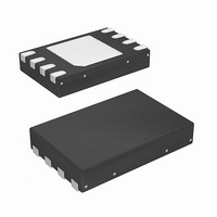
SE97BTP,547 NXP Semiconductors, SE97BTP,547 Datasheet - Page 30

SE97BTP,547
Manufacturer Part Number
SE97BTP,547
Description
IC TEMP SENSOR DIMM 8HWSON
Manufacturer
NXP Semiconductors
Datasheet
1.SE97BTP547.pdf
(53 pages)
Specifications of SE97BTP,547
Package / Case
8-WSON (Exposed Pad), 8-HWSON
Function
Temp Monitoring System (Sensor)
Topology
ADC (Sigma Delta), Comparator, Register Bank
Sensor Type
Internal
Sensing Temperature
-40°C ~ 125°C
Output Type
I²C™/SMBus™
Output Alarm
Yes
Output Fan
Yes
Voltage - Supply
3 V ~ 3.6 V
Operating Temperature
-40°C ~ 125°C
Mounting Type
Surface Mount
Temperature Threshold
+ 150 C
Full Temp Accuracy
2 C
Digital Output - Bus Interface
I2C
Digital Output - Number Of Bits
11 bit
Supply Voltage (max)
3.6 V
Supply Voltage (min)
3 V
Description/function
Temperature Sensor
Maximum Operating Temperature
+ 125 C
Minimum Operating Temperature
- 40 C
Lead Free Status / RoHS Status
Lead free / RoHS Compliant
Lead Free Status / RoHS Status
Lead free / RoHS Compliant, Lead free / RoHS Compliant
Other names
568-5055-2
NXP Semiconductors
SE97B_1
Product data sheet
8.5.2 LOWER — Lower Boundary Alarm Trip register (03h, 16-bit read/write)
8.5.3 CRITICAL — Critical Alarm Trip register (04h, 16-bit read/write)
The value is the lower threshold temperature value for Alarm mode. The data format is
2’s complement with bit 2 = 0.25 °C. RFU bits will always report zero. Interrupts will
respond to the presently programmed boundary values. If boundary values are being
altered in-system, it is advised to turn off interrupts until a known state can be obtained to
avoid superfluous interrupt activity.
Table 18.
Table 19.
The value is the critical temperature. The data format is 2’s complement with
bit 2 = 0.25 °C. RFU bits will always report zero.
Table 20.
Table 21.
Bit
Symbol
Default
Access
Bit
15:13
12
11:2
1:0
Bit
Symbol
Default
Access
Bit
15:13
12
11:2
1:0
Bit
Symbol
Default
Access
Bit
Symbol
Default
Access
Symbol
RFU
SIGN
-
RFU
Symbol
RFU
SIGN
-
RFU
LOWER - Lower Boundary Alarm Trip register bit allocation
Lower Boundary Alarm Trip register bit description
CRITICAL - Critical Alarm Trip register bit allocation
Critical Alarm Trip register bit description
RFU
RFU
8 °C
R/W
8 °C
R/W
15
15
R
R
0
0
7
0
7
0
Rev. 01 — 27 January 2010
RFU
RFU
4 °C
4 °C
R/W
R/W
14
14
R
R
0
0
6
0
6
0
Description
Sign (MSB)
reserved; always ‘0’
Description
Sign (MSB)
reserved; always ‘0’
reserved; always ‘0’
Lower Boundary Alarm Trip Temperature (LSB = 0.25 °C)
reserved; always ‘0’
Critical Alarm Trip Temperature (LSB = 0.25 °C)
DDR memory module temp sensor with integrated SPD
RFU
RFU
2 °C
R/W
2 °C
R/W
13
13
R
R
0
0
5
0
5
0
SIGN
SIGN
R/W
R/W
1 °C
1 °C
R/W
R/W
12
12
0
0
4
0
4
0
128 °C
128 °C
0.5 °C
0.5 °C
R/W
R/W
R/W
R/W
11
11
0
0
3
0
3
0
0.25 °C
0.25 °C
64 °C
64 °C
R/W
R/W
R/W
R/W
10
10
0
0
2
0
2
0
© NXP B.V. 2010. All rights reserved.
32 °C
32 °C
R/W
R/W
RFU
RFU
9
0
R
9
0
R
1
0
1
0
SE97B
16 °C
16 °C
R/W
R/W
RFU
RFU
30 of 53
8
0
R
8
0
R
0
0
0
0


