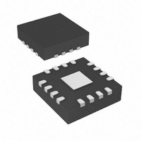
IR3505ZMTRPBF International Rectifier, IR3505ZMTRPBF Datasheet - Page 14

IR3505ZMTRPBF
Manufacturer Part Number
IR3505ZMTRPBF
Description
IC XPHASE3 CTLR 2.5A 16-MLPQ
Manufacturer
International Rectifier
Series
XPhase3™r
Datasheet
1.IR3505ZMTRPBF.pdf
(20 pages)
Specifications of IR3505ZMTRPBF
Package / Case
16-MLPQ
Mounting Type
Surface Mount
Current - Supply
3mA
Voltage - Supply
8 V ~ 16 V
Operating Temperature
0°C ~ 125°C
Applications
Processor
Supply Voltage Range
4.75V To 7.5V, 8V To 16V
Operating Temperature Range
0°C To +125°C
Digital Ic Case Style
MLPQ
No. Of Pins
16
Termination Type
SMD
Function
For High Performance CPUs And ASICs
Rohs Compliant
Yes
Filter Terminals
SMD
Controller Type
XPhase
Package
16-Lead MLPQ
Circuit
X-Phase Phase IC
Iout (a)
2.5A Gate Driver
Pbf
PbF Option Available
Lead Free Status / RoHS Status
Lead free / RoHS Compliant
Available stocks
Company
Part Number
Manufacturer
Quantity
Price
Part Number:
IR3505ZMTRPBF
Manufacturer:
IR
Quantity:
20 000
Applications information
IR3505Z EXTERNAL COMPONENTS
Inductor Current Sensing Capacitor C
The DC resistance of the inductor is utilized to sense the inductor current. Usually the resistor R
C
across the capacitor C
component of the capacitor voltage is different from that of the real inductor current. The time constant mismatch
does not affect the average current sharing among the multiple phases, but does effect the current signal ISHARE
as well as the output voltage during the load current transient if adaptive voltage positioning is adopted.
Measure the inductance L and the inductor DC resistance R
follows.
Bootstrap Capacitor C
Depending on the duty cycle and gate drive current of the phase IC, a capacitor in the range of 0.1uF to 1uF is
needed for the bootstrap circuit.
Decoupling Capacitors for Phase IC
A 0.1uF-1uF decoupling capacitor is required at the VCCL pin.
CURRENT SHARE LOOP COMPENSATION
The internal compensation of current share loop ensures that crossover frequency of the current share loop is at
least one decade lower than that of the voltage loop so that the interaction between the two loops is eliminated.
The crossover frequency of current share loop
Output Voltage Bleed Resistor
The floating high side driver draws bias current from the BOOST pin (3.5mA typical). This current flows out of
the IR3505Z through the SW pin and will charge up the output capacitor when the control IC is disabled. A
bleed resistor connected from the converter output voltage to ground is required to prevent the output voltage
from exceeding the control IC Over-Voltage protection threshold. The bleed resistor can be selected using the
following equation.
Where V
converter.
Optional phases
A converter can be designed to support more or less phases. This can be quite useful in situations where the final
load current is unknown or where increased load current may be required at some time in the future.
Figure 8 provides an application circuit that allows adjustment to the number of phases. By populating zero ohm
jumpers, or not; the number of phases can be adjusted by diverting the daisy chain timing from a 3505Z to the
next one in sequence. The effect of more or less phases on converter performance can be tested without actually
removing a 3505Z or it’s MOSFETs from the printed circuit board through use of a pull-up resistor from VCCL to
the CSIN+ pin to enable de-bug mode.
CS
in parallel with the inductor are chosen to match the time constant of the inductor, and therefore the voltage
Page 14 of 20
BLEED
is the maximum desired output voltage pre-bias and N is the number of IR3505Z used in the
CS
BST
R
CS
represents the inductor current. If the two time constants are not the same, the AC
=
L
C
CS
R
R
BLEED
L
= V
CS
and Resistor R
BLEED
is approximately 8 kHz.
/ (5.8mA x N)
CS
L
. Pre-select the capacitor C
(2)
CS
(1)
March 17, 2009
and calculate R
IR3505Z
CS
and capacitor
CS
as


