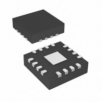
IR3505ZMTRPBF International Rectifier, IR3505ZMTRPBF Datasheet - Page 13

IR3505ZMTRPBF
Manufacturer Part Number
IR3505ZMTRPBF
Description
IC XPHASE3 CTLR 2.5A 16-MLPQ
Manufacturer
International Rectifier
Series
XPhase3™r
Datasheet
1.IR3505ZMTRPBF.pdf
(20 pages)
Specifications of IR3505ZMTRPBF
Package / Case
16-MLPQ
Mounting Type
Surface Mount
Current - Supply
3mA
Voltage - Supply
8 V ~ 16 V
Operating Temperature
0°C ~ 125°C
Applications
Processor
Supply Voltage Range
4.75V To 7.5V, 8V To 16V
Operating Temperature Range
0°C To +125°C
Digital Ic Case Style
MLPQ
No. Of Pins
16
Termination Type
SMD
Function
For High Performance CPUs And ASICs
Rohs Compliant
Yes
Filter Terminals
SMD
Controller Type
XPhase
Package
16-Lead MLPQ
Circuit
X-Phase Phase IC
Iout (a)
2.5A Gate Driver
Pbf
PbF Option Available
Lead Free Status / RoHS Status
Lead free / RoHS Compliant
Available stocks
Company
Part Number
Manufacturer
Quantity
Price
Part Number:
IR3505ZMTRPBF
Manufacturer:
IR
Quantity:
20 000
IR3505Z
PWM Ramp
Every time the phase IC is powered up PWM ramp magnitude is calibrated to generate a 50 mV/% ramp for a
VCC=12V. For example, for a 15% duty ratio the ramp amplitude is 750mV for VCC=12V. Feed-forward
control is achieved because the PWM ramp varies with VCC voltage proportionally after calibration.
In response to a load step-up the error amplifier can demand 100 % duty cycle. In order to avoid pulse
skipping under this scenario and allow the BOOST cap to replenish, a minimum off time is allowed in this
mode of operation. As shown in Figure 6, 100 % duty is detected by comparing the PWM latch output
(PWMQ) and its input clock (PWM_CLK). If the PWMQ is high when the PWM_CLK is asserted the TopFET
turnoff is initiated. The TopFET is again turned on once the RMPOUT drops within 200 mV of the VDAC.
100 % DUTY OPERATION
NORMAL OPERATION
CLKIN
PHSIN
(2 Phase Design)
EAIN
RMPOUT
VDAC+200mV
VDAC
PWMQ
80ns
Figure 7: PWM Operation during normal and 100 % duty mode.
Debugging Mode
If CSIN+ pin is pulled up to VCCL voltage, IR3505Z enters into debugging mode. Both drivers are pulled low
and ISHARE output is disconnected from the current share bus, which isolates this phase IC from other
phases. However, the phase timing from PHSIN to PHSOUT does not change.
Emulated Bootstrap Diode
IR3505Z integrates a PFET to emulate the bootstrap diode. An external bootstrap diode connected from VCCL
pin to BOOST pin can be added to reduce the drop across the PFET but is not needed in most applications.
Page 13 of 20
March 17, 2009


