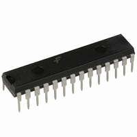
ML4425CP Fairchild Semiconductor, ML4425CP Datasheet - Page 3

ML4425CP
Manufacturer Part Number
ML4425CP
Description
IC PWM MOTOR CONTROLLER 28-DIP
Manufacturer
Fairchild Semiconductor
Datasheet
1.ML4425CSX.pdf
(16 pages)
Specifications of ML4425CP
Applications
DC Motor Controller, Brushless (BLDC)
Number Of Outputs
1
Current - Output
50mA
Voltage - Supply
10.8 V ~ 13.2 V
Operating Temperature
0°C ~ 70°C
Mounting Type
Through Hole
Package / Case
28-DIP (0.300", 7.62mm)
Mounting Style
Through Hole
Lead Free Status / RoHS Status
Lead free / RoHS Compliant
Voltage - Load
-
Lead Free Status / Rohs Status
Lead free / RoHS Compliant
PRODUCT SPECIFICATION
Pin Description
Absolute Maximum Ratings
Operating Conditions
REV. 1.0.2 7/2/01
Parameter
V
Logic Inputs (SPEED FB, BRAKE)
All Other Inputs and Outputs
Output Current (LA, LB, LC, HA, HB, HC )
Junction Temperature
Storage Temperature Range
Lead Temperature (Soldering 10 sec.)
Thermal Resistance (
Parameter
Temperature Range
ML4425CX
ML4425IX
V
DD
DD
28-Pin Narrow PDIP
28-Pin SOIC
Pin
16
17
18
19
20
21
22
23
24
25
26
27
28
SPEED FB
UV FAULT
BRAKE
Name
R
FB A
FB B
FB C
R
C
GND
C
C
C
VCO
REF
IOS
RR
RT
AT
JA
(continued)
)
An resistor to GND sets up a current proportional to the input voltage of the VCO.
A capacitor to GND sets the time that the controller stays in the align mode.
This output goes low when V
all output drivers have been disabled.
A capacitor to GND sets the time that the controller stays in the ramp mode.
Output of the back-EMF sampling circuit and input to the VCO. An RC network
connected to SPEED FB sets the compensation for the PLL loop formed by the
back-EMF sampling circuit, the VCO, and the commutation state machine.
A capacitor to between C
motor when the controller is in ramp mode.
The motor feedback voltage from phase A is monitored through a resistor divider for
back-EMF sensing at this pin.
The motor feedback voltage from phase B is monitored through a resistor divider for
back-EMF sensing at this pin.
The motor feedback voltage from phase C is monitored through a resistor divider for
back-EMF sensing at this pin.
A logic low input activates motor braking by shutting off the high-side output drivers
and turning on the low-side output drivers.
A capacitor to GND sets the time that the low-side output drivers remain off after
I
An 137k resistor to GND sets a current proportional to V
the internal bias currents except for the VCO.
Signal and power ground.
SENSE
exceeds its threshold .
RR
and SPEED FB sets the ramp rate (acceleration) of the
DD
drops below the UVLO threshold, and indicates that
GND – 0.3
GND – 0.3
Function
Min.
Min.
10.8
–40
-65
0
V
DD
Max.
Max.
13.2
±50
REF
150
150
260
14
48
75
70
85
7
+ 0.3
that is used to set all
Units
Units
°C/W
°C/W
mA
°C
°C
°C
°C
°C
V
V
V
V
ML4425
3


