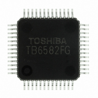
TB6582FG(O,EL) Toshiba, TB6582FG(O,EL) Datasheet - Page 4

TB6582FG(O,EL)
Manufacturer Part Number
TB6582FG(O,EL)
Description
IC BRUSHLESS MOTOR CTLR 52-QFP
Manufacturer
Toshiba
Type
3 Phase Full Wave Brushless Motor Controllerr
Datasheet
1.TB6582FGOEL.pdf
(28 pages)
Specifications of TB6582FG(O,EL)
Applications
DC Motor Controller, Brushless (BLDC), 3 Phase
Number Of Outputs
1
Voltage - Supply
6.5 V ~ 16.5 V
Operating Temperature
-30°C ~ 115°C
Mounting Type
Surface Mount
Package / Case
52-QFP
Product
Fan / Motor Controllers / Drivers
Operating Supply Voltage
15 V
Supply Current
16 mA
Mounting Style
SMD/SMT
Lead Free Status / RoHS Status
Lead free / RoHS Compliant
Current - Output
-
Voltage - Load
-
Lead Free Status / Rohs Status
Lead free / RoHS Compliant
Other names
TB6582FG(O,EL)
TB6582FGOELTR
TB6582FGOELTR
Available stocks
Company
Part Number
Manufacturer
Quantity
Price
Pin Description
Pin No.
10
31
30
14
20
19
15
22
23
29
26
28
25
27
24
18
21
12
13
17
16
32
8
4
7
6
Sys. RES
CW/CCW
FRCDRV
Symbol
D-GND
START
OSC/C
OSC/R
V
V
V
TEST
FGC
REV
V
V
WH
F
refout
WL
EP
FG
SC
UH
VH
COM
UL
VL
BRK
IP
CC
SP
ST
I/O
O
O
O
O
O
O
O
O
O
O
I
I
I
I
I
I
I
I
I
I
I
I
Power supply voltage pin V
Internal reference voltage pin 5 V (typ.)/5 mA (max)
Connected to a capacitor of 0.1 µF for power supply stabilization
Reference clock setting pin Connected to a capacitor
Reference clock setting pin Connected to a resistor
(Test pin) Reset signal input for all the logic (This pin has a pull-down resistor of 100 kΩ typ.)
High
Low
Driving output control pin. Activated to reset when any faults is detected.
(This pin has a pull-down resistor of 100 kΩ ( typ.))
High: Motor operation Low: Motor stop (Free run)
Forward/Reverse rotation select pin (This pin has a pull-down resistor of 100 kΩ typ.)
High
Low
FG output select pin (This pin has a pull-down resistor of 100 kΩ typ.)
High
Low
Rotation speed detect signal output
Selectable between 3 ppr and 1 ppr with the FGC pin.
Reverse rotation output pin
(Generates the calculated U-phase induced voltage when FGC = 2.5 V typ.)
Torque command for the reverse rotation brake control
V BRK input voltage range: 1.5 V < V BRK ≤ 2.5 V
Duty cycle = 52% when V BRK = 1.5 V
Motor speed control input (This pin has a pull-down resistor of 200 kΩ typ.)
Connection pin for a capacitor to set a ramp-up period during duty-cycle operation in DC
excitation mode
Upper arm driving signal output ±2 mAmax
Lower arm driving signal output ±2 mAmax
Upper arm driving signal output ±2 mAmax
Lower arm driving signal output ±2 mAmax
Upper arm driving signal output ±2 mAmax
Lower arm driving signal output ±2 mAmax
Test pin for the shipping inspection. (This pin has a pull-down resistor of 100 kΩ typ.)
Ground pin for digital circuits
DC excitation time setting pin
When V
When the IP pin voltage reaches 0.5 V, operating mode is switched from DC excitation to forced
commutation.
Forced commutation frequency select pin (This pin has a pull-down resistor of 100 kΩ typ.)
High
Middle
Low
(Test pin) Motor constant setting pin for induced voltage detection circuit
High
Middle or OPEN : Motor operation
Low
Voltage supply for the V
input voltage at the induced voltage detection inputs (V U , V V and V W ).
0 ≤ V
2.1 V (typ.) ≤ V
Design Specifications
SP
SP
(This pin has pull-up/down resistors of 100 kΩ typ. *2)
≤ < 2.1 V (typ.): Output Off (all phases: Low)
≥ 2.1 V (typ.), the START pin goes low to start DC excitation.
: Motor operation
: Reset
: Reverse
: Forward
:1 ppr
: 3 ppr
: Forced commutation frequency f
: Forced commutation frequency f
: Forced commutation frequency f
SP
: Low-speed oscillation (0.5 Hz)
: High-speed oscillation (30 Hz)
*) Rotation speed signal (FG) pin is always active regardless of the EP input
≤ 5.4 V (typ.): Set the PWM duty cycle according to the speed control input.
*: The CW/CCW pin must be set Low while changing the setting of this pin.
*: This pin is left Open or held at Low during actual operation of the motor.
M
voltage level shift, The voltage applied to this pin should be half the
(Square-wave mode when FGC = 2.5 V (typ.), FG = 3 ppr)
4
CC
= 6.5 V to 16.5 V
*: This pin is left Open during actual operation of the motor.
Description
ST
ST
ST
Preliminary
*: This pin is held at High under actual operation.
= f
= f
= f
osc
osc
osc
/(6 × 2
/(6 × 2
/(6 × 2
17
18
19
)
)
)
TB6582FG
2007-10-18


