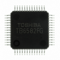
TB6582FG(O,EL) Toshiba, TB6582FG(O,EL) Datasheet - Page 3

TB6582FG(O,EL)
Manufacturer Part Number
TB6582FG(O,EL)
Description
IC BRUSHLESS MOTOR CTLR 52-QFP
Manufacturer
Toshiba
Type
3 Phase Full Wave Brushless Motor Controllerr
Datasheet
1.TB6582FGOEL.pdf
(28 pages)
Specifications of TB6582FG(O,EL)
Applications
DC Motor Controller, Brushless (BLDC), 3 Phase
Number Of Outputs
1
Voltage - Supply
6.5 V ~ 16.5 V
Operating Temperature
-30°C ~ 115°C
Mounting Type
Surface Mount
Package / Case
52-QFP
Product
Fan / Motor Controllers / Drivers
Operating Supply Voltage
15 V
Supply Current
16 mA
Mounting Style
SMD/SMT
Lead Free Status / RoHS Status
Lead free / RoHS Compliant
Current - Output
-
Voltage - Load
-
Lead Free Status / Rohs Status
Lead free / RoHS Compliant
Other names
TB6582FG(O,EL)
TB6582FGOELTR
TB6582FGOELTR
Available stocks
Company
Part Number
Manufacturer
Quantity
Price
External Parts
Note 1: These values determine the internal IC reference clock. Recommended values are required to be used for
Note 2: These are used to determine the DC excitation time and duty cycle at startup. Since those required time and
Note 3: These capacitors are used for power supply stabilization. Appropriate values must be determined depending
Note 4: The voltage generated at the phase current detection resistor R
Note 5: R
Note 6: These resistors are used for the induced voltage detection in square-wave mode. Also, these resistors are
Note 7: The time constant varies depending on the inductance and resistance of each motor. Thus, attach the motor
Note 8: The PWM signals generated from the output pins must be low-pass filtered to obtain linear voltages.
Note 9: This capacitor is used to specify the lead angle in sine-wave mode. For the automatic lead-angle correction,
Symbol
OSC/C
OSC/R
C
C
C
R
C
C
R
R
R
R
R
R
R
C
C
R
R
C
C
REF
VCC
external capacitor and resister in setting the carrier frequency at 20 KHz.
duty cycle vary depending on the motor type, appropiate values must be determined through experiments.
Since the motor is driven by a minimum current, these must be connected as close as possible to the IC
lead.
on usage environment. These capacitors must also be connected as close as possible to the IC lead to
enhance noise rejection.
generated at the induced voltage detection resistors, R
used for V
range. For a detailed functional description, refer to the functional description in Section 16, V
Supply Monitoring.
used for the detection of the voltage applied to the motor in sine-wave mode. R
so that the voltage applied to the TB6582FG becomes 4.5 V or lower.
to the TB6582 and adjust the time constant experimentally. For more details, refer to the functional
description in Section 7, Induced Voltage Detection.
the appropriate C
based on the calculated induced voltage. For more details, refer to the functional description in Section 8,
Lead Angle Correction.
SC
ST
LA
IP
1
2
3
4
5
6
7
1
2
8
9
3
4
2
and R
3
M
should be adjusted so that the voltages generated at those resistors become half the voltages
-power supply monitoring, ensure that V
Reference clock generation
(5 MHz)
DC excitation setting
V
V
Phase current detection
Motor reference detection
Induced voltage detection
Motor constant setting
Two-stage low-pass filter
Lead angle adjustment
refout
CC
power supply stabilization
LA
oscillation prevention
should be used so that the U-phase current is delayed by the amount of time obtained
Function
Design Specifications
3.3 µF (0.47 to 4.7 µF)
Recommended Value
3
(0.022 µF)
0.0039 µF
25 V/1 µF
CC
0.012 µF
0.015 pF
(0.1 µF)
0.15 µF
220 kΩ
201 kΩ
200 kΩ
360 kΩ
390 pF
0.33 Ω
6.8 kΩ
4.7 µF
11 kΩ
91 kΩ
91 kΩ
1 kΩ
2 kΩ
4
does not exceed the operating power-supply voltage
and R
5
1
, respectively. Since these voltages are also
must be below 0.5 V.
Preliminary
Remarks
(Note 1)
(Note 2)
(Note 3)
(Note 4)
(Note 5)
(Note 6)
(Note 7)
(Note 8)
(Note 9)
4
and R
5
should be adjusted
TB6582FG
2007-10-18
CC
-Power


