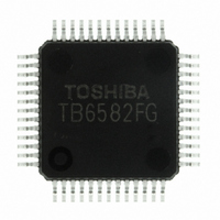
TB6582FG(O,EL) Toshiba, TB6582FG(O,EL) Datasheet - Page 10

TB6582FG(O,EL)
Manufacturer Part Number
TB6582FG(O,EL)
Description
IC BRUSHLESS MOTOR CTLR 52-QFP
Manufacturer
Toshiba
Type
3 Phase Full Wave Brushless Motor Controllerr
Datasheet
1.TB6582FGOEL.pdf
(28 pages)
Specifications of TB6582FG(O,EL)
Applications
DC Motor Controller, Brushless (BLDC), 3 Phase
Number Of Outputs
1
Voltage - Supply
6.5 V ~ 16.5 V
Operating Temperature
-30°C ~ 115°C
Mounting Type
Surface Mount
Package / Case
52-QFP
Product
Fan / Motor Controllers / Drivers
Operating Supply Voltage
15 V
Supply Current
16 mA
Mounting Style
SMD/SMT
Lead Free Status / RoHS Status
Lead free / RoHS Compliant
Current - Output
-
Voltage - Load
-
Lead Free Status / Rohs Status
Lead free / RoHS Compliant
Other names
TB6582FG(O,EL)
TB6582FGOELTR
TB6582FGOELTR
Available stocks
Company
Part Number
Manufacturer
Quantity
Price
3. Startup Control When the Motor is Stopped (Motor frequency ≤ 4 Hz)
Instructions used in each operation mode are listed below.
Reverse rotation brake
DC excitation
Forced commutation
Sensorless square-wave
Sensorless sine-wave
The TB6582FG starts the motor operation with the operation instructions from VSP input and the
operating-mode-select circuit.
At startup, since the motor is not rotating, the motor is started applying forced commutation signal,
producing the induced voltage. When the induced-voltage frequency exceeds the forced commutation
frequency specified with the status of the FST pin, the motor starts to be driven in sensorless square-wave
mode. And when the phase current frequency reaches 6 Hz or higher, and the operating mode is switched to
sensorless sine-wave mode.
At startup, the rotor is aligned to a known position and the rotation is started in forced commutation mode.
The mode switching timing from DC excitation mode to forced commutation mode can be determined by an
external capacitor.
Since the durations of DC excitation and forced commutation vary depending on the motor type and motor
loading, experiments are required for proper adjustment.
START (13 pin)
Operation Mode
V
IP (12 pin)
SC (6 pin)
SP
(7 pin)
V
DC excitation for starttup
C
V
V
V
BRK
SC
SP
SP
SP
Design Specifications
C
V
V
input voltage
input voltage
input voltage
charge voltage
SC
SP
SP
(a)
≥ 2.1 (V)
V
SC
SP
7
6
T
(b)
UP
V
0.5 V
refout
10
C
IP
IP
Instructions
12
T
C
UP
SC
R
ST
(typ.) =
× 1.1 V/2 µA (s)
DC excitation for reverse rotation
V
SP
13
input voltage
START
Clamped when the output duty
cycle reaches 35%
GND
Preliminary
TB6582FG
2007-10-18


