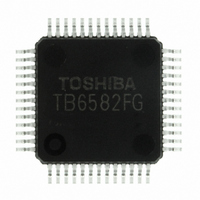
TB6582FG(O,EL) Toshiba, TB6582FG(O,EL) Datasheet - Page 11

TB6582FG(O,EL)
Manufacturer Part Number
TB6582FG(O,EL)
Description
IC BRUSHLESS MOTOR CTLR 52-QFP
Manufacturer
Toshiba
Type
3 Phase Full Wave Brushless Motor Controllerr
Datasheet
1.TB6582FGOEL.pdf
(28 pages)
Specifications of TB6582FG(O,EL)
Applications
DC Motor Controller, Brushless (BLDC), 3 Phase
Number Of Outputs
1
Voltage - Supply
6.5 V ~ 16.5 V
Operating Temperature
-30°C ~ 115°C
Mounting Type
Surface Mount
Package / Case
52-QFP
Product
Fan / Motor Controllers / Drivers
Operating Supply Voltage
15 V
Supply Current
16 mA
Mounting Style
SMD/SMT
Lead Free Status / RoHS Status
Lead free / RoHS Compliant
Current - Output
-
Voltage - Load
-
Lead Free Status / Rohs Status
Lead free / RoHS Compliant
Other names
TB6582FG(O,EL)
TB6582FGOELTR
TB6582FGOELTR
Available stocks
Company
Part Number
Manufacturer
Quantity
Price
(a)
(b)
The rotor is aligned to a certain position specified in DC excitation mode for the period of (a), during which
the IP pin voltage decreases from Vrefout to 0.5 V. The time constant for the period is determined by C
and R
cycle for DC excitation mode is determined according to the SC pin voltage. And after the IP pin voltage
falls to 0.5 V or lower, the duty cycle is determined according to the V
frequency exceeds the forced commutation frequency specified with the status of the
mode is switched to the sensorless square-wave mode.
DC excitation time
Duty cycle is determined by the gradient of SC terminal voltage, which depends on the charging of a
capacitor.
This voltage is clamped when the output duty cycle reaches about 35% for the de-excitation and
over-current protection.
When CW = U-phase → V-phase
When CCW = U-phase → W-phase
Ta (typ.) = 2.3 × C
Forced commutation time
The forced commutation is started when the IP pin voltage falls below to 0.5 V or lower.
The output duty cycle of forced commutation is determined by V
F
F
F
ST
ST
ST
ST
. After that, operation mode is switched to forced commutation mode (b) as shown above. The duty
Example)
= High
= Middle
= Low
When f
F
F
F
: Forced commutation frequency f
: Forced commutation frequency f
: Forced commutation frequency f
IP
ST
ST
ST
× R
= High
= Middle : f
= Low or Open : f
OSC
Design Specifications
ST
(s)
= 5 MHz,
: f
ST
ST
∼ − 6.4 (Hz)
∼ − 3.2 (Hz)
ST
∼ − 1.6 (Hz)
11
ST
ST
ST
= f
= f
= f
osc
osc
osc
/(6 × 2
/(6 × 2
/(6 × 2
SP
17
18
19
SP
)
)
)
input voltage.
pin voltage. When the rotational
Preliminary
FST
pin, the operation
TB6582FG
2007-10-18
IP


