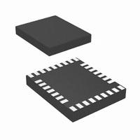
LP3950SL/NOPB National Semiconductor, LP3950SL/NOPB Datasheet - Page 23

LP3950SL/NOPB
Manufacturer Part Number
LP3950SL/NOPB
Description
IC LED DRVR WHITE BCKLGT 32-TSCP
Manufacturer
National Semiconductor
Series
PowerWise®r
Type
Backlight, White LED (I²C Interface)r
Datasheet
1.LP3950SLNOPB.pdf
(31 pages)
Specifications of LP3950SL/NOPB
Topology
PWM, Step-Up (Boost)
Number Of Outputs
6
Internal Driver
Yes
Type - Primary
Flash/Torch, LED Blinker, Light Management Unit (LMU)
Type - Secondary
RGB, White LED
Frequency
2MHz
Voltage - Supply
2.7 V ~ 2.9 V
Voltage - Output
5V
Mounting Type
Surface Mount
Package / Case
32-Laminate TCSP
Operating Temperature
-40°C ~ 85°C
Internal Switch(s)
Yes
Efficiency
90%
Led Driver Application
Mobile Phone Display Lighting, General LED Lighting
No. Of Outputs
6
Output Current
300mA
Output Voltage
5.3V
Input Voltage
3V To 7.2V
Rohs Compliant
Yes
Lead Free Status / RoHS Status
Lead free / RoHS Compliant
Current - Output / Channel
-
Other names
LP3950SL/CSP1
LP3950SLTR
LP3950SLTR
Audio Synchronization
MODE CONTROL IN THE AMPLITUDE MODE
During the amplitude synchronization mode (SYNC_MODE
= 0) the user can select between three different amplitude
mappings by using MODE_CTRL[1:0] select. These three
MODE_CTRL[1:0] = [00] = MODE0
MODE_CTRL[1:0] = [01] = MODE1
MODE CONTROL IN THE DEFAULT MODE
One of the main benefits of LP3950 is the default mode,
which enables user to build applications without I
control. The LP3950 is set to the default mode when DME
pin is high. DME pin high –state forces registers NSTBY and
EN_SYNC to the high [1] state so that the start-up sequence
get started (see start-up sequence on Section Modes of
Operation ). Function of LP3950 in the default mode of
operation is controlled by AMODE pin. If AMODE is pulled
low the LP3950 is in the amplitude synchronization mode. If
the AMODE pin is pulled high the LP3950 is in the frequency
FIGURE 20. Amplitude Synchronization Mapping Options
(Continued)
20129338
20129339
2
C or SPI
23
mapping options give different light responses as shown in
Figure 20. Again, the user can select the desired mapping
speed by SPEED_CTRL[1:0]. Maximum duty cycle is
A
audio synchronization is inactive.
MODE_CTRL[1:0] = [10] = MODE2
Note 18: This figure is for illustrating purpose only and does not necessarily
represent the accurate function of the circuit.
synchronization mode. In the default mode default control
register values are used, see Table LP3950 Control Register
Names and Default Values. Please refer to Figure 22 on
Typical Applications section at the end of this document for
wiring.
RGB OUTPUT SELECTOR
The usage of RGB outputs (RGB1 and RGB2) can be se-
lected with RGB_SEL[1:0] control bits. Audio synchroniza-
tion and RGB pattern generator output can be connected to
RGB ports as shown in the following table.
100%. If MODE_CTRL[1:0] = 11 and SYNC_MODE = 0,
20129340
www.national.com


