DS1861B+ Maxim Integrated Products, DS1861B+ Datasheet - Page 6
DS1861B+
Manufacturer Part Number
DS1861B+
Description
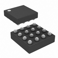
IC LASR CTRLR 1CHAN 5.5V 16CSBGA
Manufacturer
Maxim Integrated Products
Type
Laser Diode Controller (Fiber Optic)r
Datasheet
1.DS1861E.pdf
(25 pages)
Specifications of DS1861B+
Number Of Channels
1
Voltage - Supply
2.85 V ~ 5.5 V
Current - Supply
5mA
Operating Temperature
-40°C ~ 95°C
Package / Case
16-CSBGA
Mounting Type
Surface Mount
Lead Free Status / RoHS Status
Lead free / RoHS Compliant


Full Laser Control with Fault Management
NONVOLATILE MEMORY CHARACTERISTICS
(V
6
Note 1: All voltages are referenced to ground. Currents into the IC are positive, out of the IC negative.
Note 2: The threshold current (I
Note 3: Max I
Note 4: Calibration accuracy refers to the accuracy achieved at the end of calibration.
Note 5: This specification refers to the error contribution due to this chip, and does not include the error due to the drift of the mon-
Note 6: The N Temperature Drift specification includes error caused by changes in modulation current due to system temperature
Note 7: Within the APC calibration accuracy.
Note 8: Values in the table are multiplied times the I
Note 9: I
Note 10: C
Note 11: EEPROM write begins after a stop condition occurs.
Note 12: If the supply ramps up at slew rates within the specification, the device will be functional after V
Note 13: On power-up and when TX-D is deasserted, IBIASSET ramps up from zero current to its final value with ≤10% APC over-
Note 14: Modulation is applied at the level it was at before disable. If the time from disable is so long that the laser has cooled
Note 15: This parameter is guaranteed by design.
Writes
CC
_____________________________________________________________________
= +2.85V to 5.5V, T
10% and ensures the data sheet accuracies are met.
itor-diode responsivity with temperature.
variation. After the part is calibrated at +25°C, this spec allows for modulation current changes of up to +65% with increas-
ing temperature and -25% with decreasing temperature. Larger modulation current variations would have increased drift,
but this range accommodates a reasonable change (up to 2x across temperature) in laser diode slope efficiency.
Calibration is assumed to take place at +25°C for the purposes of this spec. This does not imply that the system must be
calibrated at +25°C.
dard-mode timing.
power-up time (t
shoot during the transient.
down, then meeting ER accuracy is contingent upon completion of the first ER update. The MODLOAD enable bit and
MODLOAD register can be used to load a predetermined I
section for more information.
PARAMETER
2
C interface timing shown is for fast-mode (400kHz) operation. This device is also backward compatible with I
B
—total capacitance of one bus line in pF.
CC
is dependent on SCL clock rates.
A
POAR
= 0°C to +70°C.)
) elapses.
TH
) to light producing current (I
SYMBOL
+70°C (Note 15)
BMD
set point (set by APC register) to determine the threshold limits.
CONDITIONS
APC
MODSET
) ratio should remain below 7:1. This limits overshoot to under
value if desired. See the Detailed Register Descriptions
50,000
MIN
CC
TYP
exceeds V
MAX
POA
2
UNITS
and the
C stan-
Related parts for DS1861B+
Image
Part Number
Description
Manufacturer
Datasheet
Request
R

Part Number:
Description:
Ds1861 Full Laser Control With Fault Management
Manufacturer:
Maxim Integrated Products, Inc.
Datasheet:

Part Number:
Description:
MAX7528KCWPMaxim Integrated Products [CMOS Dual 8-Bit Buffered Multiplying DACs]
Manufacturer:
Maxim Integrated Products
Datasheet:
Part Number:
Description:
Single +5V, fully integrated, 1.25Gbps laser diode driver.
Manufacturer:
Maxim Integrated Products
Datasheet:
Part Number:
Description:
Single +5V, fully integrated, 155Mbps laser diode driver.
Manufacturer:
Maxim Integrated Products
Datasheet:
Part Number:
Description:
VRD11/VRD10, K8 Rev F 2/3/4-Phase PWM Controllers with Integrated Dual MOSFET Drivers
Manufacturer:
Maxim Integrated Products
Datasheet:
Part Number:
Description:
Highly Integrated Level 2 SMBus Battery Chargers
Manufacturer:
Maxim Integrated Products
Datasheet:
Part Number:
Description:
Current Monitor and Accumulator with Integrated Sense Resistor; ; Temperature Range: -40°C to +85°C
Manufacturer:
Maxim Integrated Products
Part Number:
Description:
TSSOP 14/A�/RS-485 Transceivers with Integrated 100O/120O Termination Resis
Manufacturer:
Maxim Integrated Products
Part Number:
Description:
TSSOP 14/A�/RS-485 Transceivers with Integrated 100O/120O Termination Resis
Manufacturer:
Maxim Integrated Products
Part Number:
Description:
QFN 16/A�/AC-DC and DC-DC Peak-Current-Mode Converters with Integrated Step
Manufacturer:
Maxim Integrated Products
Part Number:
Description:
TDFN/A/65V, 1A, 600KHZ, SYNCHRONOUS STEP-DOWN REGULATOR WITH INTEGRATED SWI
Manufacturer:
Maxim Integrated Products
Part Number:
Description:
Integrated Temperature Controller f
Manufacturer:
Maxim Integrated Products
Part Number:
Description:
SOT23-6/I�/45MHz to 650MHz, Integrated IF VCOs with Differential Output
Manufacturer:
Maxim Integrated Products
Part Number:
Description:
SOT23-6/I�/45MHz to 650MHz, Integrated IF VCOs with Differential Output
Manufacturer:
Maxim Integrated Products
Part Number:
Description:
EVALUATION KIT/2.4GHZ TO 2.5GHZ 802.11G/B RF TRANSCEIVER WITH INTEGRATED PA
Manufacturer:
Maxim Integrated Products